Reference Guide
90
6A–6E VDF2 Cutoff, EG & Color
These parameters are used to set up the VDF (Variable Digital Filter) for Oscillator2. Operation is
the same as for VDF1. See “4A–4E VDF1 Cutoff, EG & Color” on page 85.
7A–7E VDF2 Velocity Sense & Keyboard Tracking
VDF2 Velocity Sensitivity parameters determine how VDF2 EG responds to note velocity. The
Keyboard Tracking parameters determine how different areas of the keyboard affect VDF2 and
VDF2 EG. Operation is the same as for VDF1. See “5A–5E VDF1 EG Velocity Sensitivity &
Keyboard Tracking” on page 87.
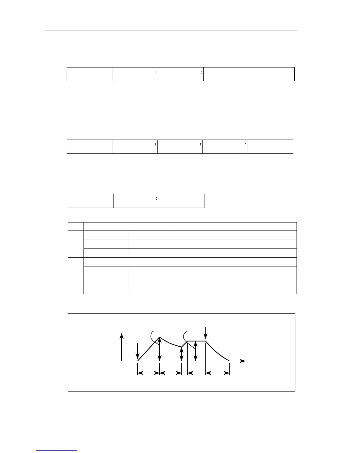
8A–8C VDA1 EG
This determines how the volume of Oscillator1 varies over time.
The following illustration shows how the VDA1 EG parameters affect the VDA (Variable Digital
Amplifier).
LCD Parameter Range Description
8A
Attack Time (AT) 0–99 Time to reach Attack Level after key pressed
Attack Level (AL) 0–99 Volume level when Attack Time ends
Decay Time (DT) 0–99 Time to reach Break Point once Attack Time ends
8B
Break Point (BP) 0–99 Volume level when Decay Time ends
Slope Time (ST) 0–99 Time to reach Sustain Level once Decay Time ends
Sustain Level (SL) 0–99 Volume level when Slope Time ends
8C Release Time (RT) 0–99 Time to reach zero volume when key released
06A VDF 2 ø
Fc=19 EGint=65
6A
6B 6C
06E Color2
Int=00 Vel=+00
6D 6E
06B VDF2 EG ø
AT09 AL=08 DT00
06C VDF2 EG ø
BP+00 ST00 SL+00
06D VDF2 EG ø
RT00 RL+00
ø
07A VDF2 V.SENSø
EGint+77 EGtm00
7A
7B 7C
07E VDF2 K.TRK
AT0 DT0 ST0 RT0
7D 7E
07B VDF2 V.SENSø
AT0 DT0 ST0 RT0
07C VDF2 K.TRK ø
KeyF#4 Mode=XALL
07D VDF2 K.TRK ø
Int=+00 EGtm=00
ø
08A VDA1 EG ø
AT00 AL99 DT15
8A
8B 8C
08C VDA1 EG
RT60
08B VDA1 EG ø
BP20 ST88 SL00
ø
Volume
Note on
Note off
Time
Sustain
Attack
Decay
Break
point
Release
Slope
Attack level
 Loading...