The PC 15-pin HD computer graphics video connector to a video acceptor
(for example, an analog display)
In the HDTV mode, the signal is outputted as a component video signal (YPbPr) and
goes out via three PINS: PIN 1 is Red or Pr, PIN 2 is Green or Y, PIN 3 is Blue or Pb. In
other modes, it is outputted as a VGA signal (RGBHV)
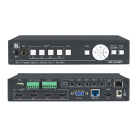
4. Connect the S/PDIF IN RCA connector to a digital audio source (for example,
a DVD player), not shown in Figure 3.
5. Connect the AUDIO LINE OUT Terminal Block connector to a balanced audio
acceptor and the S/PDIF OUT RCA connector to a digital audio acceptor.
6. Connect the SPKR OUT block connector to a pair of loudspeakers, by
connecting the left loudspeaker to the “L+” and the “L-” terminal block
connectors, and the right loudspeaker to the “R+” and the “R-” terminal block
connectors. Do not Ground the loudspeakers.
7. Connect the power cord.
We recommend that you use only the power cord that is supplied with this machine
8. If required, connect:
A PC via RS-232, see Section 5.2
The ETHERNET port, see Section 5.4