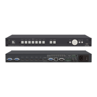
VP-734 - Connecting the VP-734
5.1 Universal Connector Pinout
This section describes the UNIV connectors from 1 to 4. Each connector can be set
as computer graphics, composite video, s-Video (Y/C) or component video.
Figure 4 and the table below define the connector pinout:
Figure 4: UNIV 15-pin HD Connector Pinout
Note that PINs 5, 6, 7, 8 and 10 are GND
5.2 Connecting to the VP-734 via RS-232
You can connect to the VP-734 via an RS-232 connection using, for example, a PC.
Note that a null-modem adapter/connection is not required.
To connect to the VP-734 via RS-232:
Connect the RS-232 9-pin D-sub rear panel port on the VP-734 unit via a
9-wire straight cable (only pin 2 to pin 2, pin 3 to pin 3, and pin 5 to pin 5
need to be connected) to the RS-232 9-pin D-sub port on your PC

 Loading...