Figures
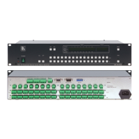
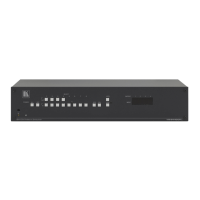
Figure 1: VS-1616A 16x16 Balanced Stereo Audio Matrix Switcher 4
Figure 2: Connecting the Balanced Stereo Audio Input/Output 7
Figure 3: Connecting the Unbalanced Stereo Audio Input 7
Figure 4: Connecting an Unbalanced Stereo Audio Output 7
Figure 5: DIP-Switch Setup on a Single Machine 8
Figure 6: Configuring a 4 Channel 16x16 Switcher with Two VS-1616A Switchers 9
Figure 7: MACHINE ADDRESS # Designation 10
Figure 8: The Principle of Assembling an Expanded Matrix Switcher 10
Figure 9: Connecting the 32x16 Switcher 12
Figure 10: Connecting the 32x32 Switcher 14
Figure 11: Assembling a System of Interconnected Switchers 15
Figure 12: Rear Panel DIP-switches 16
Figure 13: Connecting a PC to 4 VS-1616A Units 19
Figure 14: Connecting a PC (with a 25-pin connector) without a Null-modem Adapter 22
Figure 15: RS-485 Connector PINOUT 22
Figure 16: Connecting the RS-485 Connectors between 2 VS-1616A Units 23
Figure 17: An RS-485 Control Interface Setup 24
Figure 18: Keyboard Extension (EXT. KEYS) Connector 26
Figure 19: Default Startup Status Display Sequence 27
Figure 20: Sequence of MENU Commands 36
Figure 21: Choosing the MTX (SYNC from Matrix) Setting 45
Figure 22: Choosing what to INDICATE 47
Figure 23: Machine Identification 51
Tables
Table 1: Front Panel VS-1616A Features 5
Table 2: Rear Panel VS-1616A Features 5
Table 3: Quick Reference Operating Guide for a Single Machine 8
Table 4: DIP-Switch Definitions 16
Table 5: Machine # DIP-Switch Settings 17
Table 6: Summary of Basic RC-IR2 Setups 49
Table 7: Summary of Basic RC-IR2 Operations 49
Table 8: Technical Specifications of the VS-1616A Video Matrix Switcher 55
Table 9: Hex Table for the VS-1616A Video Matrix Switcher 56