5 Installation at Site
22 of 64
Etaline
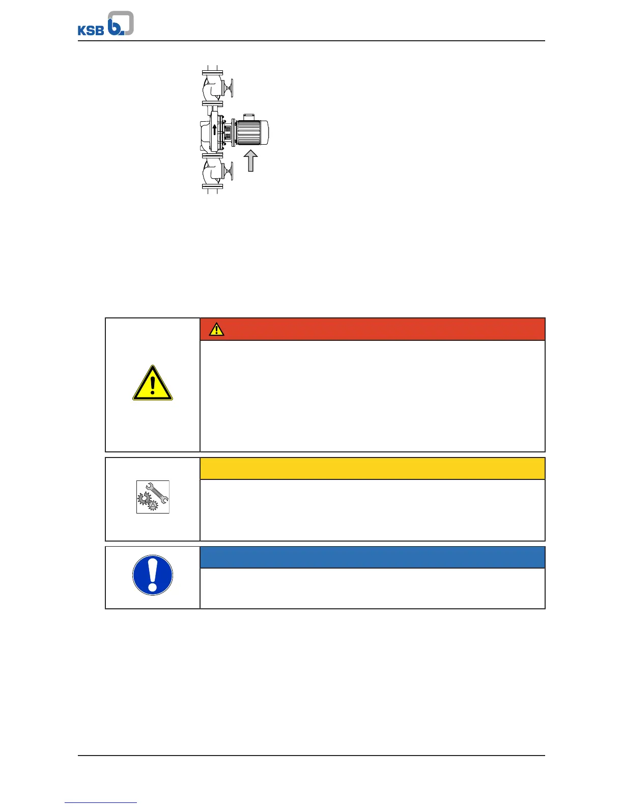
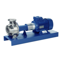
Fig.6: Supporting the motor
1. Position the pump set on the foundation or in the piping and fasten it.
2. Place a spirit level on the discharge nozzle to align the pump set.
3. Change the position of the plugs for the condensation drain holes (if any) at the
motor, depending on the installation position.
5.3 Piping
5.3.1 Connecting the piping
DANGER
Impermissible loads acting on the pump nozzles
Danger to life from escaping hot, toxic, corrosive or flammable fluids!
▷ Do not use the pump as an anchorage point for the piping.
▷ Anchor the pipes in close proximity to the pump and connect them properly
without transmitting any stresses or strains.
▷ Observe the permissible forces and moments at the pump nozzles.
(ðSection5.3.2,Page24)
▷ Take appropriate measures to compensate for thermal expansion of the piping.
CAUTION
Incorrect earthing during welding work at the piping
Destruction of rolling element bearings (pitting effect)!
▷ Never earth the electric welding equipment on the pump or baseplate.
▷ Prevent current flowing through the rolling element bearings.
NOTE
Installing check and shut-off elements in the system is recommended, depending on
the type of plant and pump. However, such elements must not obstruct proper
drainage or hinder disassembly of the pump.
ü Suction lift lines have been laid with a rising slope, suction head lines with a
downward slope towards the pump.
ü A flow stabilisation section having a length equivalent to at least twice the
diameter of the suction flange has been provided upstream of the suction flange.
ü The nominal diameters of the pipelines are at least equal to the nominal
diameters of the pump nozzles.
ü Adapters to larger diameters have a diffuser angle of approximately 8° to
prevent excessive pressure losses.
ü The pipelines have been anchored in close proximity to the pump and connected
without transmitting any stresses or strains.