5 Installation at Site
24 of 64
Etaline
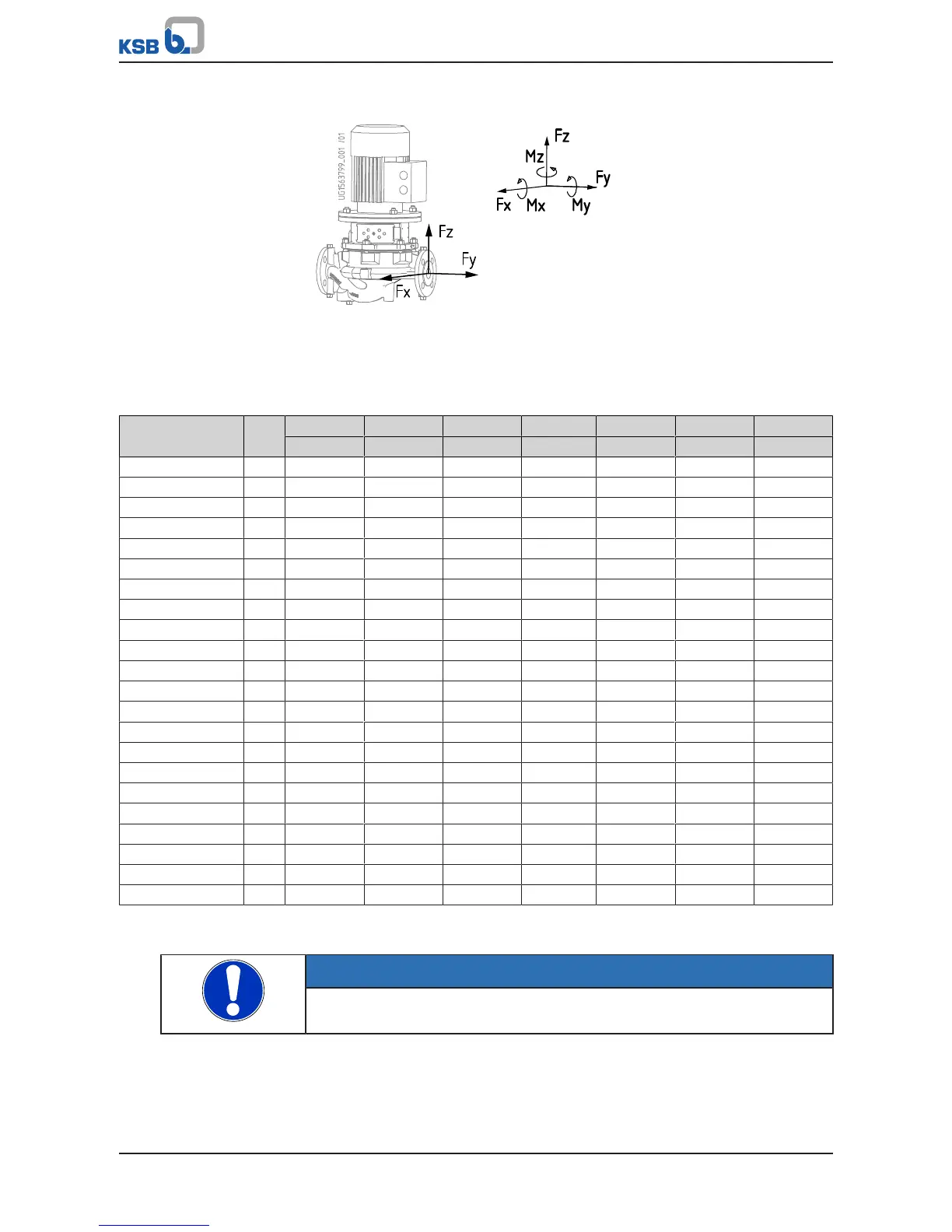
5.3.2 Permissible forces and moments at the pump nozzles
Fig.8: Forces and moments at the pump nozzles
The data on forces and moments apply to static piping loads only. The values are only
applicable if the pump is installed on a baseplate and bolted to a rigid and level
foundation.
Table8: Forces and moments at the pump nozzles
Size DN F
x
F
y
F
z
∑F M
x
M
y
M
z
[N] [N] [N] [N] [Nm] [Nm] [Nm]
032-032-160 32 320 370 300 574 390 265 300
032-032-200 32 320 370 300 574 390 265 300
040-040-160 40 400 450 350 696 450 320 370
040-040-250 40 400 450 350 696 450 320 370
050-050-160 50 530 580 470 916 500 350 400
050-050-250 50 530 580 470 916 500 350 400
065-065-160 65 650 740 600 1153 530 390 420
065-065-250 65 650 740 600 1153 530 390 420
080-080-160 80 790 880 720 1385 560 400 460
080-080-200 80 790 880 720 1385 560 400 460
080-080-250 80 790 880 720 1385 560 400 460
100-100-125 100 1050 1180 950 1843 620 440 510
100-100-160 100 1050 1180 950 1843 620 440 510
100-100-200 100 1050 1180 950 1843 620 440 510
100-100-250 100 1050 1180 950 1843 620 440 510
125-125-160 125 1250 1400 1120 2186 740 530 670
125-125-200 125 1250 1400 1120 2186 740 530 670
125-125-250 125 1250 1400 1120 2186 740 530 670
150-150-200 150 1600 1750 1400 2754 880 610 720
150-150-250 150 1600 1750 1400 2754 880 610 720
200-200-250 200 2100 2350 1900 3680 1150 800 930
200-200-315 200 2100 2350 1900 3680 1150 800 930
5.3.3 Vacuum balance line
NOTE
Where fluid has to be pumped out of a vessel under vacuum, installing a vacuum
balance line is recommended.
The following rules apply to vacuum balance lines:
▪ Minimum nominal line diameter 25 mm.
▪ The line extends above the highest permissible fluid level in the vessel.