11 / 125Issued: 16.03.2016 Version: MA KR 300 470-2 PA V5
3 Product description
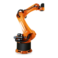
Link arm The link arm is the assembly located between the arm and the rotating column.
It is mounted on one side of the rotating column via the gear unit of axis 2 and
is driven by an AC servomotor. During motion about axis 2, the link arm moves
about the stationary rotating column. The cable harness of the electrical instal-
lations is routed inside the link arm and is mounted in hinged clamps.
Rotating column The rotating column houses the motors of axes 1 and 2. The rotational motion
of axis 1 is performed by the rotating column. It is screwed to the base frame
via the gear unit of axis 1. The AC servomotor for driving axis 1 is mounted
inside the rotating column. The counterbearing for the counterbalancing sys-
tem is integrated into the rear of the rotating column housing. The fork slots
are also screwed to the rotating column if the robot is transported using a fork
lift truck.
Base frame The base frame is the base of the robot. It is screwed to the mounting base.
The interfaces for the electrical installations and the energy supply systems
(accessory) are housed in the base frame. The base frame and rotating col-
umn are connected via the gear unit of axis 1. The flexible tube for the electri-
cal installations and the energy supply system is accommodated in the base
frame.
Counterbal-
ancing system
The counterbalancing system is installed between the rotating column and the
link arm and serves to minimize the moments generated about axis 2 when the
robot is in motion and at rest. A closed, hydropneumatic system is used. The
system consists of two accumulators, a hydraulic cylinder with associated hos-
es, a pressure gauge and an accumulator safety valve as a safety element to
protect against overload. The accumulators correspond to category II, fluid
group 2, of the Pressure Equipment Directive.
Electrical installa-
tions
The electrical installations are described in Chapter .
Options The robot can be fitted and operated with various options, such as energy sup-
ply systems for axes 1 to 3, energy supply systems for axes 3 to 6, or working
range limitation systems. The options are described in separate documenta-
tion.
 Loading...