Printed Circuit Boards
Function Overview
2-5
Front Panel PCBs Function Summaries
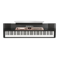
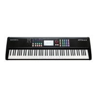
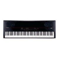
The SP5-8 Front Panel PCBs perform the following functions:
1. ScanPort interface to front panel LEDs
2. ScanPort interface to front panel buttons
3. ScanPort interface to the keyboard
4. MIDI In/Out connector interface to logic level signals
5. DC power entry socket, power switch connector, and voltage regulators
6. USB connector interface
7. LCD contrast voltage adjuster
8. CC Pedal and Switch Pedals interface
9. ScanPort interface to Pitch and Mod wheels
10. ScanPort interface to the Volume control and control sliders
11. Audio dierential ampliers for Left/Right output jacks
12. Amplier for Headphones jack
13. ScanPort analog multiplexor
14. Audio Muting circuits
The following function summary descriptions reference the SP5-8 Right Front Panel PCB,
Rev A, schematic circuit drawings (Chapter 7, pages 7-8 and 7-9) and the SP5-8 Left Front
Panel PCB, Rev. A, schematic circuit drawings (Chapter 7, pages 7-10 and 7-11).
In the SP5-8, the main CPU on the Engine PCB also performs scanning of the keyboard, LEDs,
and controls. This is done through the ScanPort connector, a simple, Kurzweil standardized,
CPU independent interface for scanning.
The Right Front Panel PCB and the Left Front Panel PCB help the Engine PCB communicate
with the SP5-8’s LEDs, buttons, sliders, Spin knob, power supply, keyboard, wheels, and
rear panel connections. Most of the subsystems on the Right Front Panel PCB and Left Front
Panel PCB connect to the ScanPort. The Right Front Panel PCB and the Left Front Panel PCB
connect via the Control Panel Bridge connectors.

 Loading...