Bottom Enclosure
Removing the Wheels Assembly
4-13
Bottom Enclosure
The bottom enclosure includes the Wheels Assembly and Keyboard Assembly.
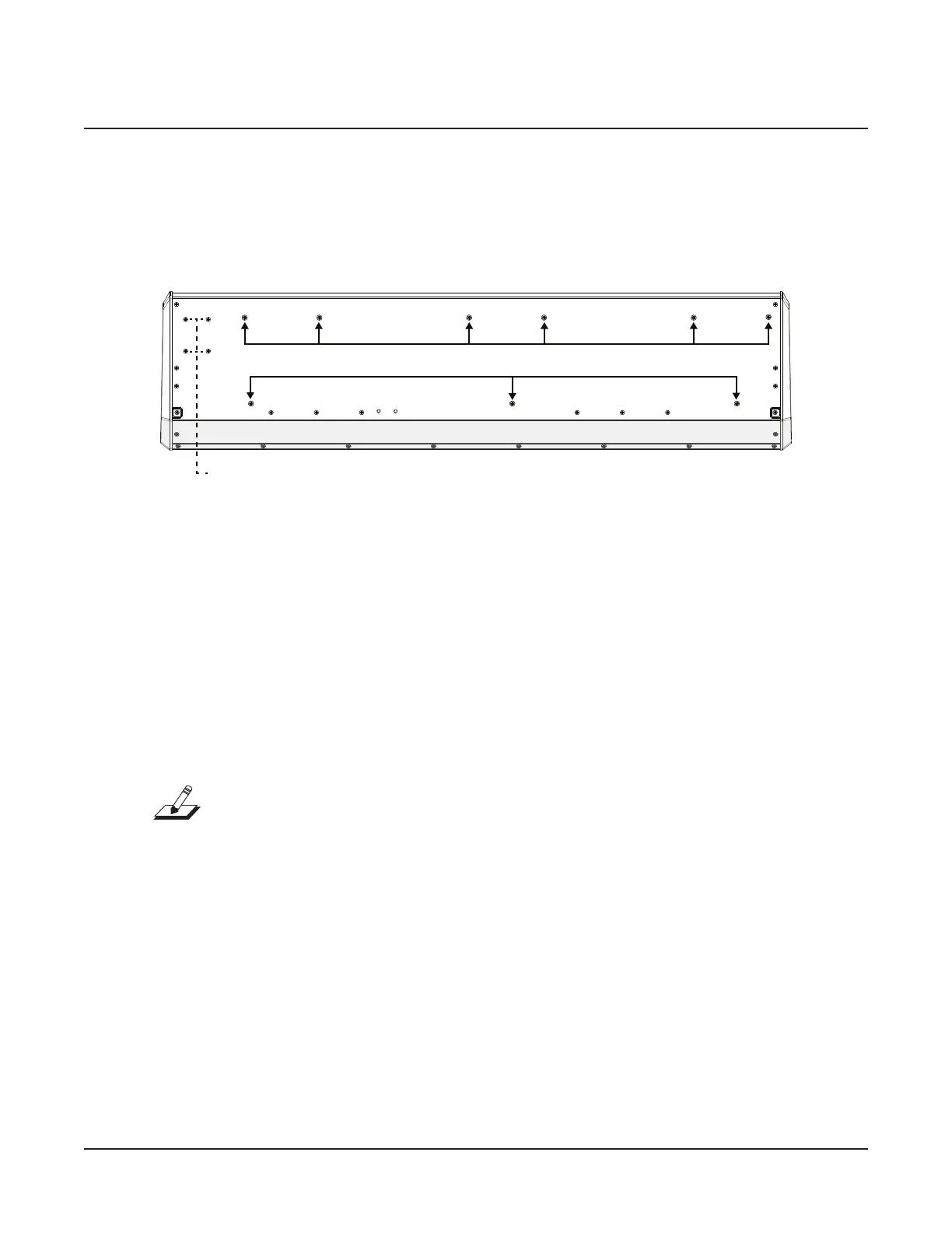
rear keyboard screws
Rear Panel
front keyboard screws
Figure 4-9 Wheels Assembly and Keyboard Assembly hardware locations
Removing the Wheels Assembly
The following procedure assumes that you have completed the instructions on page 4-2
through page 4-4 to open the SP5-8 and remove the top enclosure.
1. Refer to Figure 4-9. Slide the left front corner of the SP5-8 forward o of your work
surface to access the four screws securing the Wheels Assembly to the bottom enclosure.
Remove the four screws.
2. Slide the unit back onto your work surface.
Note: The stranded wire cable connecting the Mod and Pitch wheels to the Left Front
Panel PCB is bundled (using tie wraps) with the Aftertouch stranded wire cables. Tape
secures the cable bundle to the bottom enclosure. Tape also secures the Aftertouch ex
cables and their connection to the Aftertouch stranded wire cables. Always peel back the
tape from one side to free the cable(s).
3. Lift the Wheels Assembly up, approximately two inches. Tape (at two locations) secures
the Aftertouch ex cable(s) to the bottom enclosure. Peel back the tape from one side
to free the cable(s). Disconnect the Aftertouch ex cables from the Aftertouch stranded
wire cables. Be sure to mark one or both cables and connectors to distinguish between
the white and black pressure strips.
4. Disconnect the J20 from the Left Front Panel PCB.
5. Remove the tape, cut the tie wraps, and free the Wheels Assembly stranded wire cable.
6. Remove the Wheels Assembly.

 Loading...