Top Enclosure
Removing the Right Front Panel PCB
4-8
Removing the Right Front Panel PCB
1. Follow the procedure to remove the top enclosure.
Note: Prepare your work surface. Be sure to place the top enclosure on foam or other
soft surface to prevent damage or scratches to the rotary and slide potentiometers,
switch buttons, the LCD, and front panel.
2. Place the top enclosure face down on your work surface.
3. Remove the three screws that secure the enclosure support wall and set the wall aside.
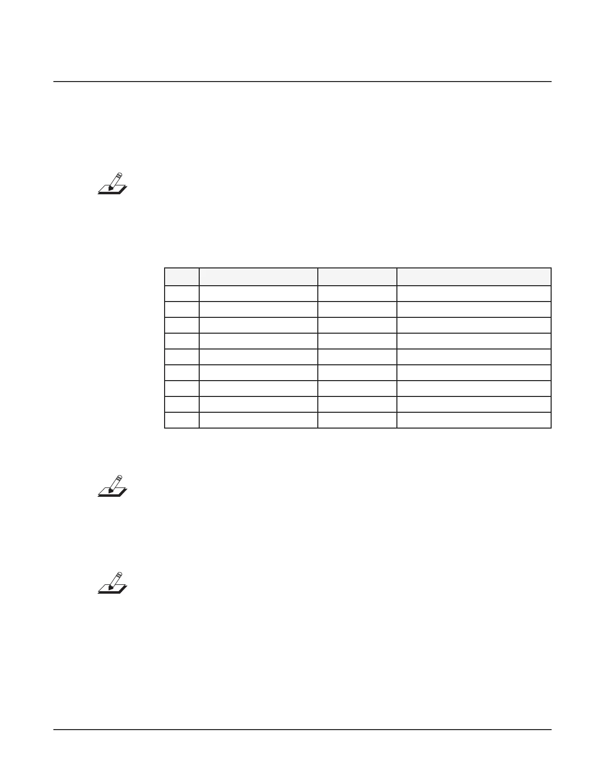
4. Following Steps 5 and 6, disconnect the cables listed in Table 4-3.
Ref. Name Cable Type Destination
J1 ScanPort at ribbon Engine PCB
J3 Keyboard Treble at ribbon Keyboard Assembly
J4 MIDI stranded wire Engine PCB
J5 Keyboard Bass at ribbon Keyboard Assembly
J6 Power Switch stranded wire Power Switch Assembly
J8 USB stranded wire Engine PCB
J9 DC Power Out shielded wire Engine PCB
J10 USB stranded wire Engine PCB
J19 Control Panel Bridge at ribbon Left Front Panel PCB
Table 4-3 Right Front Panel PCB cables
Note: If a at ribbon cable has a connector with tabs to secure it, squeeze the tabs
inward and disconnect the cable. If a at ribbon cable uses a locking cable clip, remove
the clip and set it safely aside.
5. Disconnect the at ribbon cables in the following order:
J19, Control Panel Bridge; J1, Scan Port; J5, Keyboard Bass; J3, Keyboard Treble.
Note: When you disconnect the Bass and Treble at ribbon cables, feel free to mark
the cables designating B for Bass and T for Treble to avoid reversing the cables when
reconnecting.
6. Disconnect the remaining shielded and stranded wire cables in the following order:
J4, J10, J8, J6, and J9.
7. Unwrap the tab of the cable wrap (see Figure 4-7) so that you can move the bundled
cables.
8. Remove the ve remaining screws that secure the Right Front Panel PCB to the top
enclosure. One screw also secures the cable wrap. Keep the cable wrap with the screw.

 Loading...