Top Enclosure
Replacing the Engine PCB
4-7
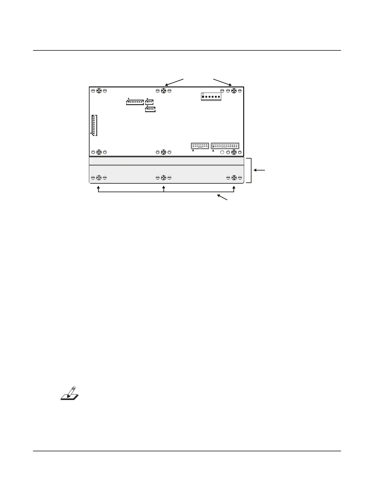
Figure 4-6
J11
Audio A
J31
MIDI/CPU
J14
J26
J7 ScanPort
J23
Power Conn
Engine PCB
J19
Char LCD
plate
cable wrap
do not remove
Engine PCB connector and hardware locations
5. Unwrap the cable wraps at the locations noted in Figure 4-6.
6. The front edge (normally closest to the keyboard) of the Engine PCB is mounted on
plate that is secured to the top enclosure. When you remove the Engine PCB, it is not
necessary to remove the plate.
7. Remove the six screws that secure the Engine PCB to the top enclosure and mounting
plate. Two of these screws also secure a cable wrap. When you remove the screws, keep
the cable wraps with them.
8. Remove the Engine PCB.
Replacing the Engine PCB
1. Place the Engine PCB in position on the top enclosure and mounting plate.
2. Install the six screws to secure it. Be sure to install the cable wraps at the locations noted
in Figure 4-6.
3. Connect the stranded wire cable to J23.
4. Connect at ribbon cable from J1 on the Right Front Panel PCB to J7 on the Engine PCB.
5. Connect at ribbon cable from the LCD to J19 on the Engine PCB.
Note: If the at ribbon cables use locking cable clips, be sure to install them.
6. Connect the stranded wire and shielded wire cables in the following order:
J26, J14, J31, and J11
7. Be sure the cables are properly routed and bundled. Wrap the exible tab of the cable
wraps to secure the cables.

 Loading...