Top Enclosure
Removing the Left Front Panel PCB
4-11
Inside the Top Enclosure
4. Removing the Left Front Panel PCB requires removing the LCD. Follow the procedure
on page 4-10 and remove the LCD.
5. Following Steps 6–9, disconnect the cables listed in Table 4-2.
Ref. Name Cable Type Destination
J1 Key Pressure (White) stranded wire Keyboard Assembly
J2 Key Pressure (Black) stranded wire Keyboard Assembly
J7 Audio from Engine shielded wire Engine PCB
J20 Wheels stranded wire Wheels Assembly
J25 Control Panel Bridge at ribbon Right Front Panel PCB
Table 4-4 Left Front Panel PCB cables
Note: If a at ribbon cable has a connector with tabs to secure it, squeeze the tabs
inward and disconnect the cable. If a at ribbon cable uses a locking cable clip, remove
the clip and set it safely aside.
6. Disconnect the at ribbon cable from J25.
7. Disconnect the stranded wire cables in the following order:
J2, J1, and J20.
8. Disconnect the shielded wire cable from J7.
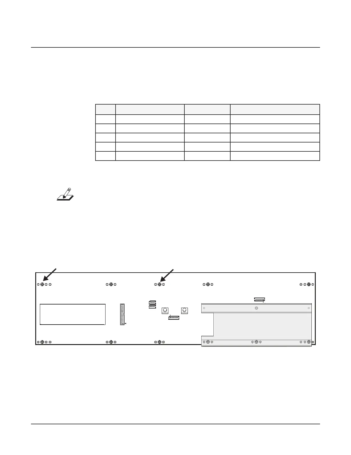
Figure 4-8
J25
Control
Panel
Bridge
Wheels
J20
J1 Pressure White
J2 Pressure Black
J7 Audio from Engine
LCD
opening
enclosure support wall
Left Front Panel PCB connector and hardware locations
9. Remove the three screws that secure the enclosure support wall and set the wall aside.
10. Remove the eight remaining screws that secure the Left Front Panel PCB to the top
enclosure. Two of these screws also secure cable wraps. Keep the cable wraps with the
screws.
11. Remove the Left Front Panel PCB. The LEDs, switch buttons, sliders, and other
components are now accessible.

 Loading...