2C9
2-3-6
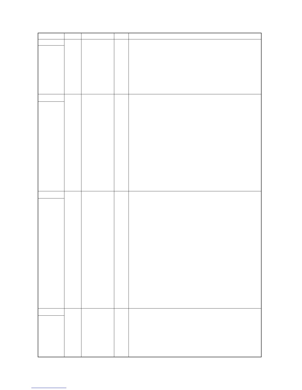
Connector Pin No. Signal I/O Description
YC4
Connected
to the
operation
unit PCB
YC5
Connected
to the
operation
unit PCB
YC6
Connected
to the
enginge
PCB
YC7
Connected
to the APC
PCB
1 +5 V O 5 V DC power supply for OPCB
2 BUZERDRN O OPCB buzer signal
3 SCAN7N O Key switch scan signal 7
4 SCAN6N O Key switch scan signal 6
5 SCAN5N O Key switch scan signal 5
6 SCAN4N O Key switch scan signal 4
7 SCAN3N O Key switch scan signal 3
8 SCAN2N O Key switch scan signal 2
9 SCAN1N O Key switch scan signal 1
10 SCAN0N O Key switch scan signal 0
1 LED0 O LED lighting selection signal 0
2 LED1 O LED lighting selection signal 1
3 LED2 O LED lighting selection signal 2
4 LED3 O LED lighting selection signal 3
5 LED4 O LED lighting selection signal 4
6 LED5 O LED lighting selection signal 5
7 LED6 O LED lighting selection signal 6
8 LED7 O LED lighting selection signal 7
9 LED8 O LED lighting selection signal 8
10 LED9 O LED lighting selection signal 9
11 LED10 O LED lighting selection signal 10
12 LED11 O LED lighting selection signal 11
13 LED12 O LED lighting selection signal 12
14 KEY0 I Key switch return signal 0
15 KEY1 I Key switch return signal 1
16 KEY2 I Key switch return signal 2
17 KEY3 I Key switch return signal 3
18 KEY4 I Key switch return signal 4
1 +12 V I 12 V DC power supply from EPCB
2 OVSYNC I Original scanning interval signal
3 RSTN I Reset signal
4 EGRN I Enginge communication EGRN signal
5 SDIR I Enginge communication SDIR signal
6 SBSY I Enginge communication SBSY signal
7 PDMASKN I Printing image interval signal
8 EGSI O Enginge serial communication transmission
9 SCKN O Enginge communication clock signal
10 EGSO I Enginge serial communication reception
11 PLGCLK O PM clock signal
12 S.GND - Ground
13 OUTEPN I Laser diode output signal
14 +5 V I 5 V DC power supply from EPCB
15 +5 V I 5 V DC power supply from EPCB
16 +5 V I 5 V DC power supply from EPCB
17 S.GND - Ground
18 S.GND - Ground
19 S.GND - Ground
20 +5 V3 I 5 V DC power supply from EPCB
21 P.GND - Ground
22 +24 V I 24 V DC power supply from EPCB
1 PDN I Laser sync signal
2 S.GND - Ground
3 OUTPEN O Laser diode output signal
4 SAMPLEN O Laser light signal
5 VDON O Image differential signal (negative)
6 VDOP O Image differential signal (positive)
7 +5 V3 O 5 V DC power supply for APCPCB
 Loading...


