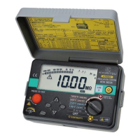
Items – Panel side Description
①
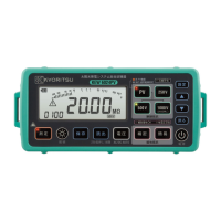
LCD LCD with backlight
②
Test button Starts/ stops a continuous measurement
③
Backlight button Turns on/ off the backlight
④
Save button Saves the measured result
⑤
Read/ delete button Reads out or deletes the saved data
⑥
Voltage button Measures voltages
⑦
Buttons for earth resistance
measurement
Selects simplified or precision earth
resistance measurement .
⑧ LED for aux. earth
Lights up in earth measurement to show the
auxiliary earth electrodes are connected properly.
⑨ Earth voltage warning LED
Lights up in earth measurement if the earth voltage
is relatively high.
⑩ Power button
Powers on/ off the instrument.
(A long press: 1 sec. or longer)
⑪ Back button Returns to the previous step at setting.
⑫
Down (cursor) button Decreases setting values.
⑬
Up (cursor) button Increases setting values.
⑭
Setup button Configures each setting.
⑮
LED for live circuit warning Alerts the circuit to be tested is live.
⑯
Button for insulation
resistance measurement
Selects insulation resistance measurement for PV
system or for the other objects.
⑰
Button for rated measure-
ment voltages
Selects a measurement voltage for insulation
resistance measurement. (A long press of
2 sec or longer is required to select 1000V.)
Items – Terminal part
Designated function
⑱
● LINE
● EARTH
● PV/ ordinary insulation measurement
● Earth (simplified) measurement
● Voltage measurement
⑲
● C(H)
● P(S)
● E
● Earth (precision) measurement
⑳
OPTICAL ADAPTER
For a connection of MODEL8212USB
to transfer saved data to PC
w ww . .com
information@itm.com1.800.561.8187
 Loading...