25
•
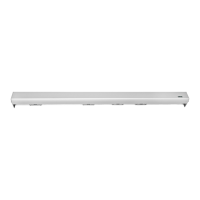
TERMINAL BOARD M4 (Inputs 14, 15, 16, 17, 18, 19)
19 = Input COMMON.
16 = AUX 1 auxiliary. N.O. contact. Provides ve functions depending on the
conguration set on the control unit:
a) Using the mechanical key selector EV-MSEL for the selection of the door
work program (F01=ON), connect terminal 16 to terminal 3 of the mechanical
selector.
b) If the digital selector ET-DSEL is present, the activation of the AUX 1 input
causes door closure and Night lock function activation, bypassing the setting
of the digital selector ET-DSEL.
c) If INTERLOCK operation between two Label automatic doors is enabled
(F27=ON), the activation of the AUX1 input by‑passes the interlock function
(see the “Interlock system” paragraph).
d) Input of third closure safety sensor E.C.3. N.C. Contact
The operation of the third closure safety sensor must be enabled by the
ET-DSEL digital selector (function F54 = ON).
If the door detects the presence of an obstacle during closure, it stops and reopens.
If the door detects the presence of an obstacle during pause, it remains open.
e) Input for door lock button from inside in the privacy function (see paragraph
"Privacy Function").
14 = STOP/INTERLOCK input. Input contact logic state can be set to either N.O. or
N.C. using the digital selector ET-DSEL (function F24).
The input can be used for three dierent purposes, according to the conguration
set on the control unit:
a) Stop command to stop door motion.
b) detection of the interlock signal to prevent the door from opening when the
interlock function is enabled (function F27=ON). In this case the input must be
set as N.C..
c) connection of a door closing device allowing to forcibly close the door when
the function F52 ON is set. In this case the input must be set as N.C..
15 = LOCK1 input N.O. contact The activation of the input activates the output of
module UR24 if option A was selected on the multiple function F41m or F45m (see
paragraph "Module UR24").
17 = AUX 2 auxiliary. N.O. contact. Contact used for three functions depending on the
conguration set:
a) Using the mechanical key selector EV-MSEL for the selection of the door
work program (F01=ON), connect terminal 17 to terminal 4 of the mechanical
selector.
b) It can be used as a door opening command in all automatic door work
programs.
c) Input of fourth closure safety sensor E.C.4. N.C. Contact
The operation of the fourth closure safety sensor must be enabled by the
ET-DSEL digital selector (function F55 = ON).
If the door detects the presence of an obstacle during closure, it stops and
reopens.
If the door detects the presence of an obstacle during pause, it remains open.
18 = OPEN input. Input contact logic state can be set to either N.O. or N.C. using the
digital selector ET-DSEL (function F23).
The activation allows opening the door in all operating programs.
•
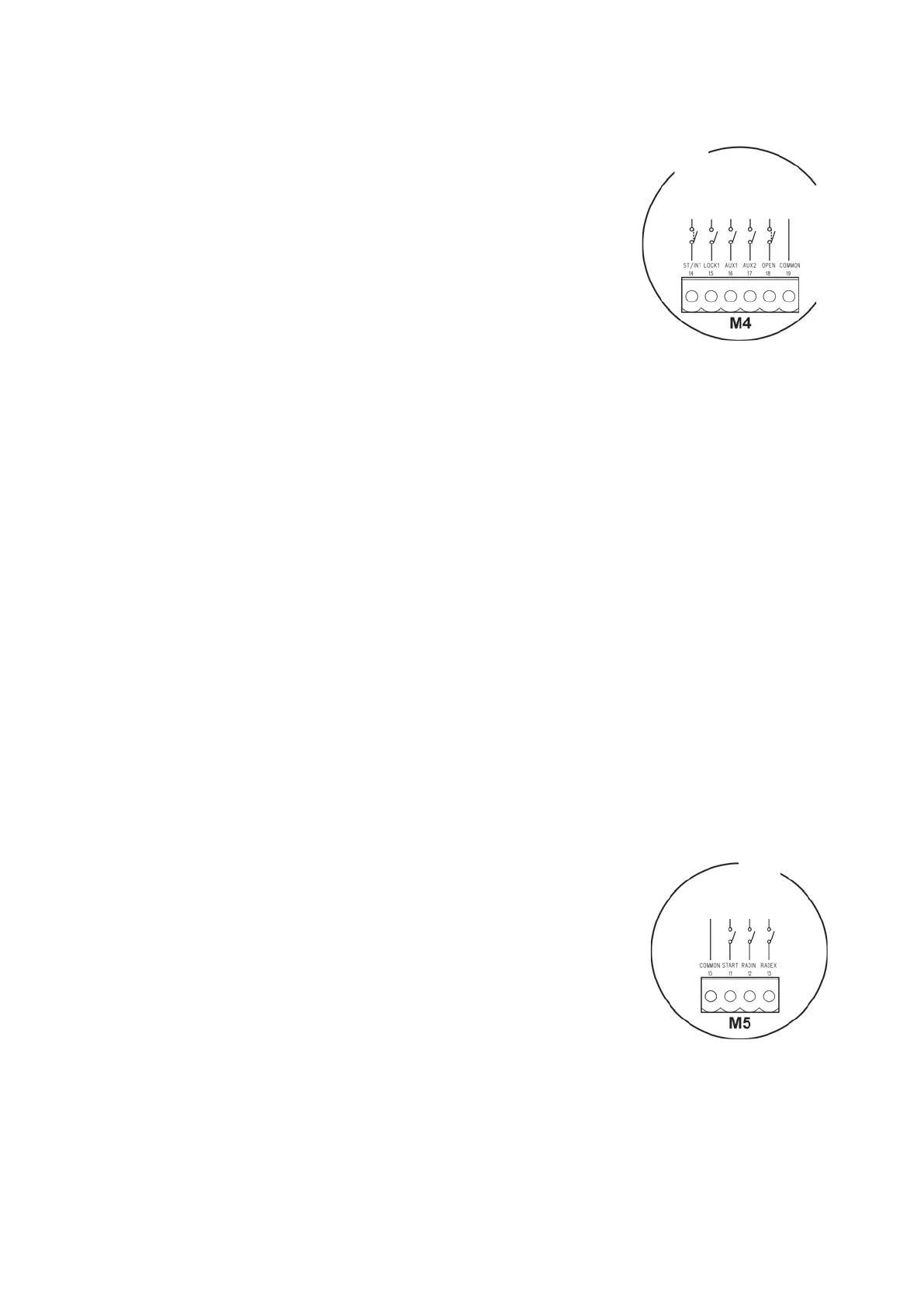
TERMINAL BOARD M5 (Inputs 10, 11, 12, 13)
10 = Input COMMON.
12 = INTERNAL RADAR input. N.O. contact.
Activation causes door opening. It is not active when the program selector is set
to "Entry only" or "Night lock".
13 = EXTERNAL RADAR input. N.O. contact.
Activation causes door opening. It is not active when the program selector is set
to "Exit only" or "Night lock".
11 = START input. N.O. contact.
The activation opens the door in all operating programs (if F38 = OFF).
The START input is disabled in “NIGHT LOCK” mode (if F38 = ON).
COMMON
START
INTERNAL RADAR
EXTERNAL RADAR
STOP/INTERLOCK
LOCK1
AUX1
AUX2
OPEN
COMMON