9
5) COVER
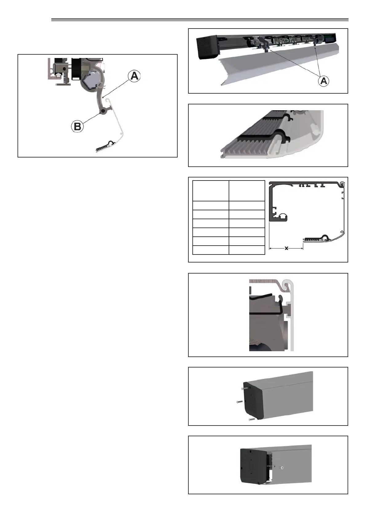
To remove completely the automation cover, press the terminal
end of the pins (B) of the support articulations and remove them
pulling them from the opposite side (FIG.1)
Manually support the cover before extracting the pin.
In the lower section of the cover you can install an optional
adjustable closing prole allowing to close the gap between the
door and the cover, thus improving the look of the automation.
To adjust the adjustable closing prole depth you must detach the
cover from the automation and put it on a at surface FIG. 3.
Arrange the adjustable closing prole as shown in the gure and
fasten it to the cover by means of the special clips.
Select the ideal adjustment of the adjustable closing prole,
referring to Fig.4 and secure each of the plastic clips, entering rst
the teeth of the clip in the slot of the adjustable closing prole and
then push, pushing forward the top of the clip until the engagement
on the cover is achieved.
Ret the cover on the automation, retting the support articulations
with the specic pins, then close the cover on the automation
engaging the top part with the transom FIG.5.
The cover of the automation ETERNA 150 features two support
links (A) specially designed to ensure that it remains stable in the
opening position.
FIG. 1
Fasten the cover by means of the screws on the side caps FIG.6.
If the transom is ush with the wall, it is possible to secure the
cover on the front, drilling a hole corresponding to the front seat
prearranged on the side cap and secure the cover by means of
the specic Kit EV-KFCF (option) FIG.7.
FIG. 2
FIG. 7
FIG. 3
FIG. 5
FIG. 6
FIG. 4
No. of
engagement
teeth
height X
8 66.8
7 62.7
6 58.5
5 54.4
4 50.2
3 46.1
SIDE CAP SIDE VIEW
SIDE PANEL FRONT VIEW