Lake Shore Model 340 Temperature Controller User’s Manual
Options and Accessories 10-5
10.3 MODEL 3462 DUAL STANDARD INPUT OPTION CARD
The Model 3462 Input Card adds two standard inputs to the Model 340 Temperature Controller. The inputs
appear as C & D on the display. The original standard inputs remain fully functional.
10.3.1 Field Installation
The Model 3462 Option kit adds two optional sensor inputs to the Model 340 instrument rear panel. It
includes:
• (1) 10-conductor Ribbon Cable
• (1) 3462 Option Card
• (4) 1¼-inch metal standoffs
• (8) 4-40 machine screws
Required tools: Small Phillips-head screwdriver and 5/64-inch Allen Wrench.
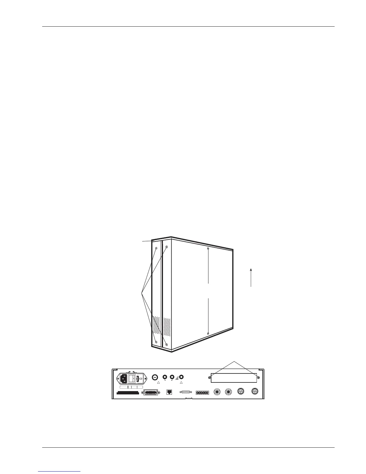
1. Turn Model 340 power switch OFF. Unplug power cord from wall outlet, then instrument.
2. Stand the unit on its face. Use the Allen wrench to remove the 4 screws on each side of the covers.
3. Use the small Phillips screwdriver to remove any top and bottom cover screws; instruments may have
1 or 2 screws on the top and bottom covers.
4. Remove rear plastic bezel. The covers are tracked. Slide the top and bottom covers to the rear on the
tracks to remove them.
5. Remove rear panel option plate screws and set aside. Remove rear panel option plate.
SIDE COVER
SCREWS
(On Both Sides)
REAR PLASTIC
BEZEL
TOP COVER SCREWS
(Remove bottom
cover screws also)
To remove top
and bottom
covers, slide
them to the rear
on the tracks.
DIGITAL I/O
ANALOG
OUT 1
ANALOG
OUT 2
SERIAL I/O
120
IEEE-488 INTERFACE
S
H1 AH1 T5 L4 SR1 RL1 PP0 DC1 DT0 C0 E1
RELAYS
NC C NO NC C NO
LO HI
HEATER FUSE
2.5 A
HEATER OUTPUT
LOHI
DATA CARD
FUSE
DATA
-10% +5%
50-60 Hz
175 VA MAX
LINE 100 / 120
2.0 A
.25x1.25in SB
220 / 240
1.0 A
5x25mm SB
OFF ON
INPUT A
l+
V+
l-
V-
INPUT B
l+
V+
l-
V-
60V MAX
WARNING
NO USER SERVICEABLE PARTS INSIDE. REFER
SERVICING TO TRAINED SERVICE PERSONNEL.
!
WARNING
FOR CONT5INUED PROTECTION AGAINST FIRE HAZARD,
REPLACE FUSE WITH SAME TYPE AND RATING.
!
EXT
REAR PANEL
OPTION PLATE SCREWS
OPTION PLATE
Figure 10-5. Cover and Option Plate Screws