Lake Shore Model 340 Temperature Controller User’s Manual
5-4 Measurement Operation
To select a temperature response curve, press the Input Setup key. The input setup setting screen will
appear with the input letter in the top left hand corner. Use the s or t key to select an input. Press the Enter
key or the Next Setting key to display the input parameters for that input. Press the Next Setting key until
the curve field is highlighted and then use s or t key to select a curve from the list. Press the Enter key or
the Next Setting key and to advance to the next parameter. (If curve selection was not successful, press the
Next Setting key and verify the appropriate type selection). Press the Save Screen key to store the changes
in the Model 340.
Table 5-3. Standard Curve Table
Curve Setting No. Sensor Type Model Number Curve Name Temp. Range Table
DT-470 1 Silicon Diode DT-470 Curve 10 1.4 – 475 K A-1
DT-500-D 2 Silicon Diode *DT-500-DRC-D Curve D 1.4 – 365 K
DT-500-E1 3 Silicon Diode *DT-500/DRC-E1 Curve E1 1.4 – 330 K
A-2
PT-100 4 Platinum RTD 100 PT-100 DIN 43760 30 – 800 K
PT-1000 5 Platinum RTD 1000 *PT-1000 DIN 43760 30 – 800 K
A-3
Type K 6 Thermocouple Type K Type K
3.15 – 864 K (1500 K
†
)
A-4
Type E 7 Thermocouple Type E Type E
3.15 – 622 K (930 K
†
)
A-5
Type T 8 Thermocouple Type T Type T 3.15 – 670 K A-6
AuFe .03% 9 Thermocouple Chromel-AuFe 0.03% Chromel-AuFe 0.03% 3.50 – 500 K A-7
AuFe .07% 10 Thermocouple Chromel-AuFe 0.07% Chromel-AuFe 0.07% 3.15 – 610 K A-8
DT-670 11 Silicon Diode DT-670 DT-670 1.4 – 500 K A-9
* Curves supported but sensors no longer available through Lake Shore.
†
Temperature range extended when using ±50 mV Range.
5.3 FILTER AND MATH
Some simple arithmetic features have been included in the Model 340 as a convenience to the user. Filter,
Max, Min and linear equation can be applied to an input reading. As shown in Figure 5-1, the filter can be
applied to all readings for an input. The results of Max, Min, and linear equation can be shown on the display
in combination with the actual input reading. The display format screen is used to configure the display.
5.3.1 Filter
The Model 340 can apply an averaging filter to any sensor input. The filter is designed to prevent electronic
noise that is picked up on the sensor lead wires from showing on the display. It is enabled or disabled for all
of the reading formats of an input at the same time. A number of readings filtered and filter reset window can
be changed by the user to meet their application. The control equation has a filter that is enabled
independently from the input filter.
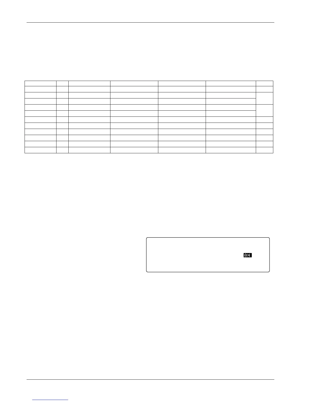
To turn on the filter for an input, press the Math
Setup key. The MATH COMPUTATIONS screen
appears with the Input field highlighted. Use the
s or t key to select an input. Use the Enter or
Next Setting key to move the cursor to FILTER
Enable. Use the s or t key to select ON. The
default setting is On.
The user may change filter behavior by changing the number filter readings. Although more filter readings
settle the display reading more, it is not always appropriate to select many filter readings. More filter readings
also slow display reading response to real temperature changes in the load.
To change on the filter readings (points) for an input, press the Math Setup key. You see the MATH
COMPUTATIONS screen. The Input field is highlighted. Use the s or t key to select an Input. Use the
Enter or Next Setting key to move the cursor to FILTER Points. Use the s or t key to select the desired
number. The minimum number of points is 2, the maximum is 64. The default setting is 10.
Some users do not want the filter to slow the response of the display reading when large deliberate changes
in temperature are made. The filter window parameter allows the user to set the limit for a large temperature
change. If an unfiltered reading differs from the filtered reading by more than the filter window limit, the filter
will be restarted. The filter window limit is set in percent of full scale range for the selected input type.
To change the filter window for an input, press the Math Setup key. You will see the MATH
COMPUTATIONS screen. The Input field will be highlighted. Use the s or t key to select an Input. Use the
Enter or Next Setting key to move the cursor to FILTER Window. Use the s or t key to select the desired
percentage. The minimum is 1%, the maximum is 10%. The default setting is 1%.
Enable:
Source:
Enable:
Points:
Window:
ON
TEMP K
ON
10
1%
<more>MATH SETUP
MAX/MIN FILTER
Input: A