Lake Shore Model 340 Temperature Controller User’s Manual
Service 11-3
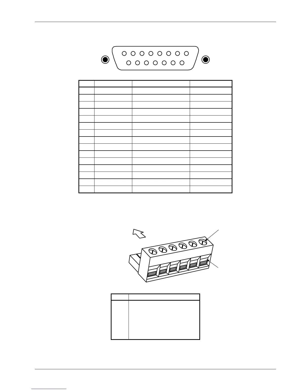
54321
15 14 13 12
DIGITAL I/O
876
11 10 9
340-11-3.eps
Pin Symbol Description Type or Limit
1 DO1 Digital Output 1 TTL Output
2 DO2 Digital Output 2 TTL Output
3 DO3 Digital Output 3 TTL Output
4 DO4 Digital Output 4 TTL Output
5 DO5 Digital Output 5 TTL Output
6 Reserved/DI6 Acting as Digital Input 6 TTL Input
7 +5 V +5 Volts Output 100 mA max
8 +15 V +5 Volts Output 50 mA max
9 DI1 Digital Input 1 TTL Input
10 DI2 Digital Input 2 TTL Input
11 DI3 Digital Input 3 TTL Input
12 DI4 Digital Input 4 TTL Input
13 DI5 Digital Input 5 TTL Input
14 -15 V -15 Volt Output 50 mA max
15 Gnd Ground -
Figure 11-2. DIGITAL I/O DA-15 Rear Panel Connector Details
Slides into RELAYS slot
in rear of Model 340
Use screwdriver to
lock or unlock wires
Insert wire into slot
1
2
3
4
5
6
Screw Terminal Connector
Lake Shore P/N 106-737
PIN DESCRIPTION
1
2
3
4
5
6
Low, Normally Closed (N.C.)
Low, Common
Low, Normally Open (N.O.)
High, Normally Closed (N.C.)
High, Common
High, Normally Open (N.O.)
Figure 11-3. RELAYS LO & HI Rear Panel Connector Details