Lake Shore Model 340 Temperature Controller User’s Manual
Front Panel Operation 4-1
CHAPTER 4
FRONT PANEL OPERATION
4.0 GENERAL
This chapter covers turning power on in Paragraph 4.1, display formats in Paragraph 4.2, keyboard
description in Paragraph 4.3, keypad navigation in Paragraph 4.4, and changing display format in
Paragraph 4.5. Be sure to read Paragraph 3.3 on line voltage verification before proceeding.
4.1 TURNING POWER ON
Once the line voltage setting has been verified (Paragraph 3.3), plug the instrument end of the line cord
(included in the connector kit) into the back of the instrument. Then plug the opposite end of the cord into a
properly grounded, three-prong receptacle. Place the power switch, located next to the line cord connector, to
the On position. The display backlight will brighten the display area and a Lake Shore graphic logo will appear
on the display. The alarm beeper will sound once and the instrument will show a display of sensor readings
and control settings.
There are several types of feedback that may be present at this time. Some indicate a problem with the
instrument and others indicate the need for the user to setup the sensor inputs or control loops. Problems are
indicated by the following:
• The display backlight does not turn on (backlight is dim indicating a cold instrument).
• The display does not show a logo or change from the logo.
• An error window appears with a message about a hardware problem. Refer to Paragraph 11.9.
• The alarm beeper does not sound.
• Instrument does not respond to keys being pressed.
If any of these symptoms are observed, please contact the factory.
Messages that indicate the need for further setup are common when first powering up the unit because many
users do not have temperature sensors installed or sensor type selected. Do not be concerned if the following
appear: overload condition, no sensor attached, no temperature response curve selected, or words
indicating a problem with the heater configuration in the area of the display that normally shows heater output.
These problems will be resolved as instrument setup is completed.
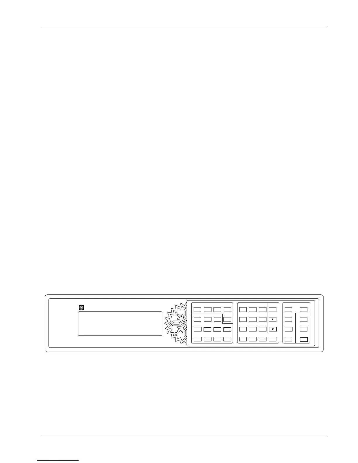
340 Temperat ur e Controller
Loop 2
Pr o gra m
Loop 1
Setpoint
Zone
Settings
Con trol
Channel
Au to
Tun e
Ramp
Con t ro l
Setup
Manual
Outpu t
PI
D
Heater
Of f
+/-
Sav e
Sc r e e n
Help
Dat aCa rd
Lo ca l
Can ce l
Sc r e en M o r e
Inpu t
Setup
Display
For mat
Sof tCal
Escape
Sc an
Setup
Int er f a c e
Alarm
Res et
Ma th
Res et
Options
En t er
Analog
Outputs
Alarm
Setup
Ma th
Setup
789
456
123
0
.
+/-
Curv e
En t r y
Previous
Setting
Nex t
Sett ing
Heater
Rang e
LakeShore
340-1-1.eps
Figure 4-1. Model 340 Front Panel
4.2 DISPLAY FORMATS
The Model 340 has an eight line by 40 character LCD graphic display capable of showing small (6
× 8) and
large (12 × 16) characters. This display is very flexible and provides the user feedback at each step of
operation. The normal display of the Model 340 shows sensor readings and control status. Other specialized
displays are used for instrument settings, data entry, help and error messages.
The normal display is discussed in Paragraph 4.2.1. Setting displays is discussed in Paragraph 4.2.2. Data
entry displays are discussed in Paragraph 4.2.3. Finally, error displays are discussed in Paragraph 4.2.4.