Lake Shore Model 340 Temperature Controller User’s Manual
11-6 Service
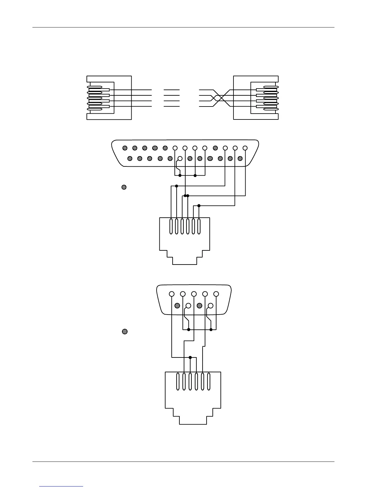
11.5 SERIAL INTERFACE CABLE AND ADAPTERS
To aid in Serial Interface troubleshooting, wiring information for the serial cable assembly and the two mating
adapters are provided in Figures 11-8 thru 11-10. The Model 2001 and 2003 are included with the Model 340.
The Model 2002 is an option.
BLACK
RED
GREEN
YELLOW
RxD
Gnd
Gnd
TxD
12
3
4
56
12
345
6
C-340-11-8.eps
Figure 11-8. Model 2001 RJ-11 Cable Assembly Wiring Details
131211109 876543 21
25 24 23 22 21 20 19 18 17 16 15 14
= Not Used
654321
DB-25 Connector
RJ-11
Receptacle
RxD
Gnd
TxD
For Customer-supplied
computer with DB-25
Serial Interface
Connector configured
as DCE. If the interface
is DTE, a Null Modem
Adapter is required to
exchange Transmit and
Receive lines.
C-340-11-9.eps
Figure 11-9. Model 2002 RJ-11 to DB-25 Adapter Wiring Details
5 4321
9876
= Not Used
654321
DB-9 Connector
RJ-11
Receptacle
Gnd
RxD
TxD
For Customer-supplied
computer with DE-9
Serial Interface
Connector configured
as DTE. If the interface
is DCE, a Null Modem
Adapter is required to
exchange Transmit and
Receive lines.
C-340-11-10.eps
Figure 11-10. Optional Model 2003 RJ-11 to DE-9 Adapter Wiring Details