Lake Shore Model 340 Temperature Controller User’s Manual
Measurement Operation 5-1
CHAPTER 5
SENSOR INPUT AND
TEMPERATURE MEASUREMENT OPERATION
5.0 GENERAL
This chapter describes front panel operation for sensor input configuration and temperature measurement.
The user must setup temperature sensor input before a valid sensor reading can be made, and select a
temperature response curve to convert readings to temperature. This chapter covers sensor input setup in
Paragraph 5.1, selecting a temperature response curve in Paragraph 5.2, filter and math functions in
Paragraph 5.3, and scanner support in Paragraph 5.4.
5.1 SENSOR INPUT SETUP
This section covers sensor type in Paragraph 5.1.1, voltage excitation in Paragraph 5.1.2, thermal
EMF compensation with voltage excitation in Paragraph 5.1.3, special sensor type configuration in
Paragraph 5.1.4, and turning an input off in Paragraph 5.1.5.
5.1.1 Sensor Type
The first step in sensor input configuration is setting the sensor type parameter. The Model 340 works with
a variety of different sensors, each with special requirements for excitation and input range. Selections for
several different types of sensors are pre-programmed into the Model 340. If using one of these sensor types,
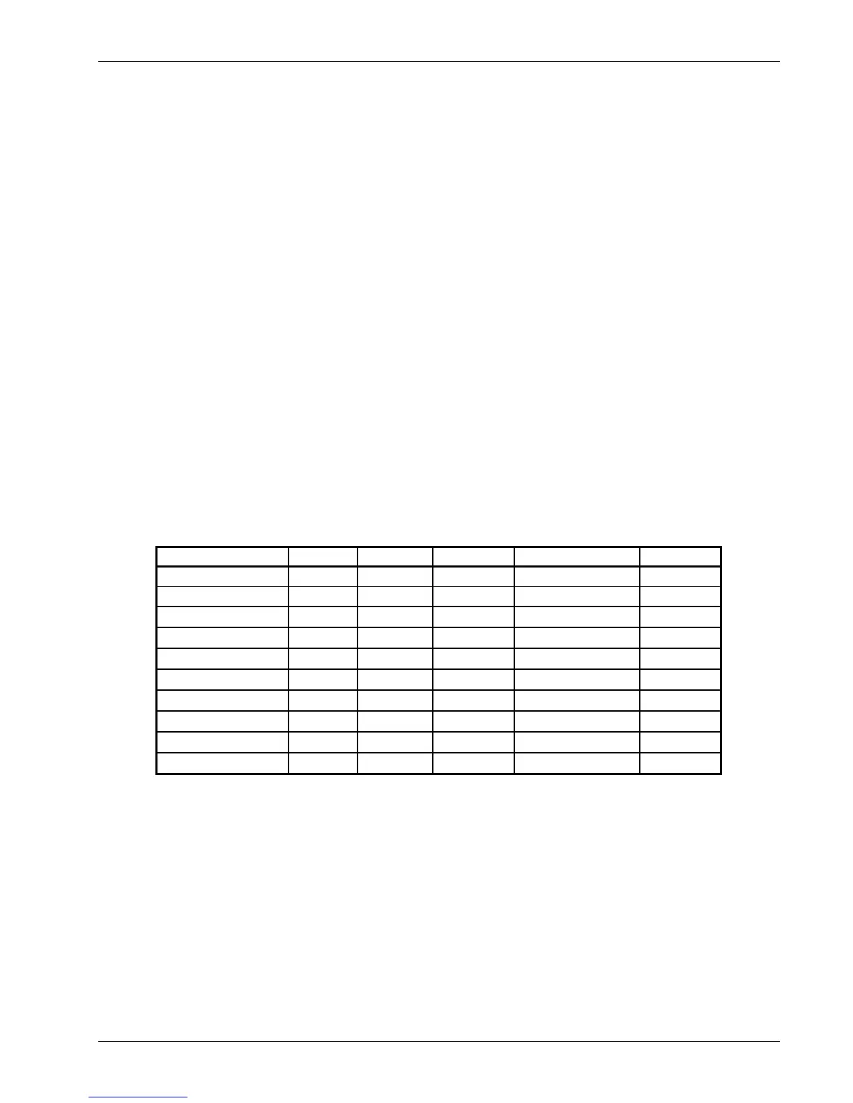
select that type to automatically change the associated parameters listed in Table 5-1.
Table 5-1. Sensor Types Recognized by the Model 340
Type Units Excitation Range Temp. Coefficient Update
Silicon Diode volts 10 µA 0-2.5 V Negative 20 Hz
GaAlAs Diode volts 10 µA 0-7.5 V Negative 20 Hz
Platinum 100/250 ohms 1 mA
0-250 Ω
Positive 20 Hz
Platinum 100/500 ohms 1 mA
0-500 Ω
Positive 20 Hz
Platinum 1000 ohms 100 µA
0-2500 Ω
Positive 20 Hz
Rhodium-Iron ohms 1 mA
0-250 Ω
Positive 20 Hz
*Carbon-Glass ohms 10 mV
0-300 kΩ
Negative 10 Hz
*Cernox ohms 10 mV
0-300 kΩ
Negative 10 Hz
*Ruthenium Oxide ohms 10 mV
0-300 kΩ
Negative 10 Hz
*Germanium ohms 1 mV
0-30 kΩ
Negative 10 Hz
* Refer to Paragraph 5.1.2 for voltage excitation for these sensors. Approximate temperature ranges are given
with specifications. Other sensor types are available with input option cards.
To select a pre-programmed sensor type, press Input Setup. The input setup setting screen appears with the
input letter in the top left hand corner. Use the s or t key to select an input. Press Enter or Next Setting to
display the input parameters. Press Next Setting until the type field highlights and then use the s or t key to
select one of the sensor types in the table above. Press Enter or Next Setting to show the input parameters
for that sensor type. To proceed to temperature response curve selection (Paragraph 5.2), press Previous
Setting or press Save Screen to store the changes in the Model 340. The default setting is Silicon Diode.
NOTE: If the user changes any of the parameters listed for a standard sensor type, the
instrument assumes a special sensor type is required (Paragraph 5.1.4).
NOTE: Use the display setup screen (Paragraph 4.5) to show configured readings from an input
on the display.