Lake Shore Model 340 Temperature Controller User’s Manual
Front Panel Operation 4-5
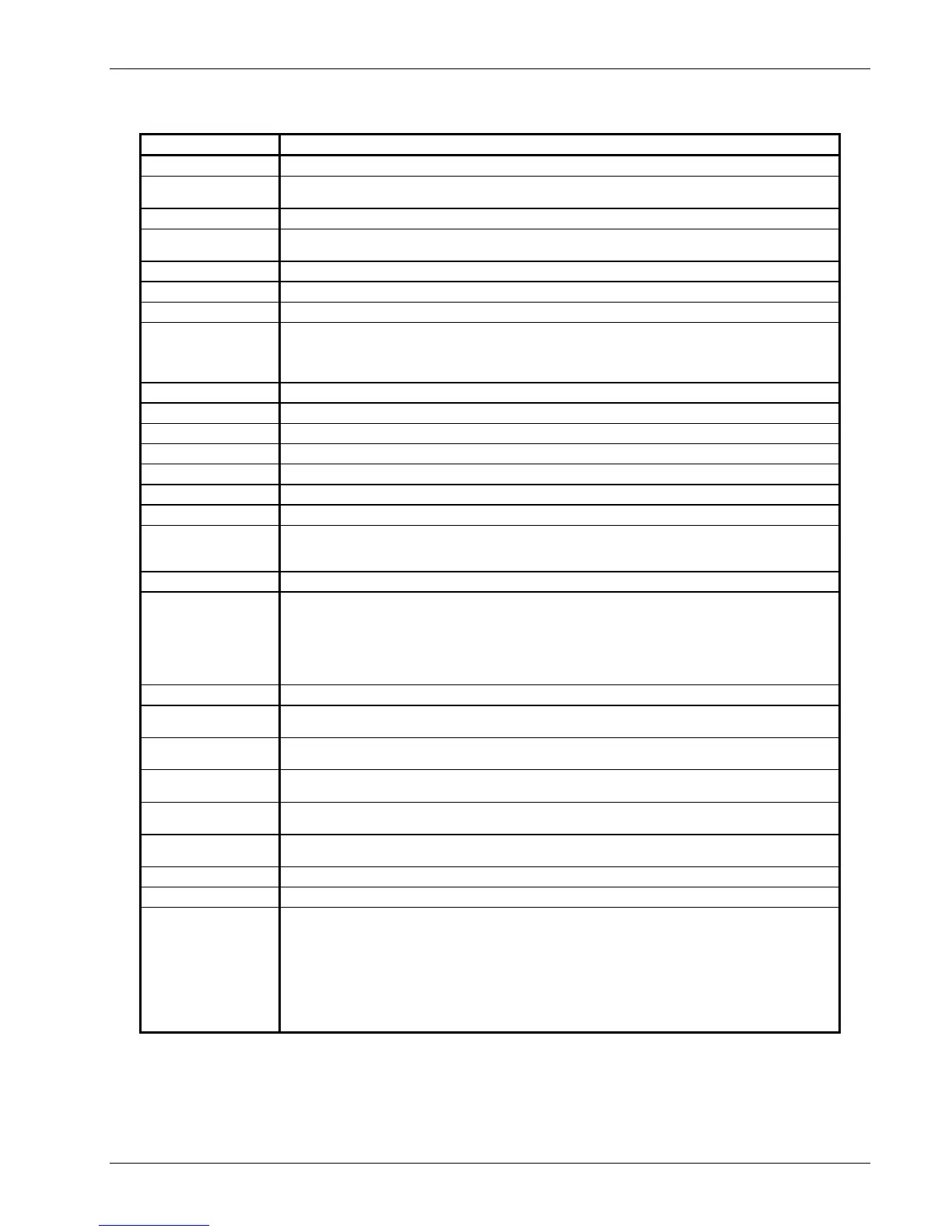
4.4.7 Key Definitions
Key Description
AutoTune
Displays the AUTO TUNE screen to set Auto P, Auto PI, or Auto PID control mode.
Zone Settings
Displays the ZONE SETTINGS screen which specifies P, I, D, Manual Output, and
Heater Range for up to 10 Temperature control zones.
Ramp
Displays the RAMP SETUP screen which turns ramp on or off and selects ramp rate.
Program
Displays the PROGRAM MODE screen. Allows the user to Run an internal program,
Terminate a program, Edit a program, or Clear program memory.
P
Allows direct setting of the proportional (P) control parameter.
I
Allows direct setting of the integral (I) control parameter.
D
Allows direct setting of the derivative (D) control parameter.
Control Setup
Displays the CONTROL SETUP screen which enables the control loop, establishes
power up status and setpoint units, sets heater resistance and control mode, and turns
the filter on or off. Press the More key to display the CONTROL LIMITS screen which
sets the temperature, slope, maximum heater current, and range.
Heater Range
Allows direct setting of Loop 1 heater range.
Heater Off
Immediately turns off Loop 1 heater.
Control Channel
Allows direct setting of the sensor feedback channel for a control loop.
Loop 1
Displays Control Loop 1 parameters and status on lower three lines of display.
Loop 2
Displays Control Loop 2 parameters and status on lower three lines of display.
Setpoint
Allows direct setting of control setpoint.
Manual Output
Allows direct setting of manual output control parameter.
Input Setup
Displays the INPUT SETUP screen which selects the sensor type and curve number.
Other sensor parameters can be overwritten, but this changes sensor status to
"Special." Only curves appropriate to the sensor type display.
SoftCal
Displays the SOFTCAL screen which accepts and stores SoftCal curves.
Display Format
Displays three screens (use the More key to toggle between the screens):
1. The READING DISPLAY FORMAT screen sets the number of readings (1 thru 8)
shown in the normal display and assigns an input and data source to each.
2. The CONTROL DISPLAY FORMAT screen sets lower three lines of the display.
3. The MISC. DISPLAY FORMAT screen sets display contrast, back lighting, and
keypad lock.
Scan Setup
Displays the EXTERNAL SCANNER SETUP screen to set external scanner support.
Curve Entry
Displays the CURVE ENTRY screen which edits, copies, or erases temperature
response curves.
Interface
Displays the COMPUTER INTERFACE screen which sets IEEE-488.2 and Serial
interface parameters.
Alarm Setup
Displays the ALARM SETTINGS screen which enables or disables alarms and sets
various alarm parameters.
Math Setup
Displays the MATH COMPUTATIONS screen which sets Max/Min and Filter
parameters. Press the More key to see the LINEAR EQUATION screen.
Analog Outputs
Displays the ANALOG OUTPUTS screen which specifies Mode, Bipolar, Status, and
other parameters for Analog Output A and B.
Alarm Reset
Immediately resets all latched alarms.
Math Reset
Immediately resets all Max and Min values.
Options
Displays four screens:
1. The DIGITAL I/O screen manually sets the digital inputs and outputs.
2. The RELAY & BEEPER SETUP screen allows the user to choose alarm or manual
control for relays and to turn the beeper on or off.
3. The DATE & TIME screen is used to set real-time clock.
4. The REVISION INFORMATION screen displays the controller serial number and
revision history.
Use the More key to toggle between the screens.