5 Installation
54
5.2.3 Electrical connection of the LT 2/KS1-DK lambda transmitter
DANGER
Before all work on electrical equipment, switch off the power supply voltage to the
equipment and check that it has been isolated. Compliance with the relevant safety
provisions is essential.
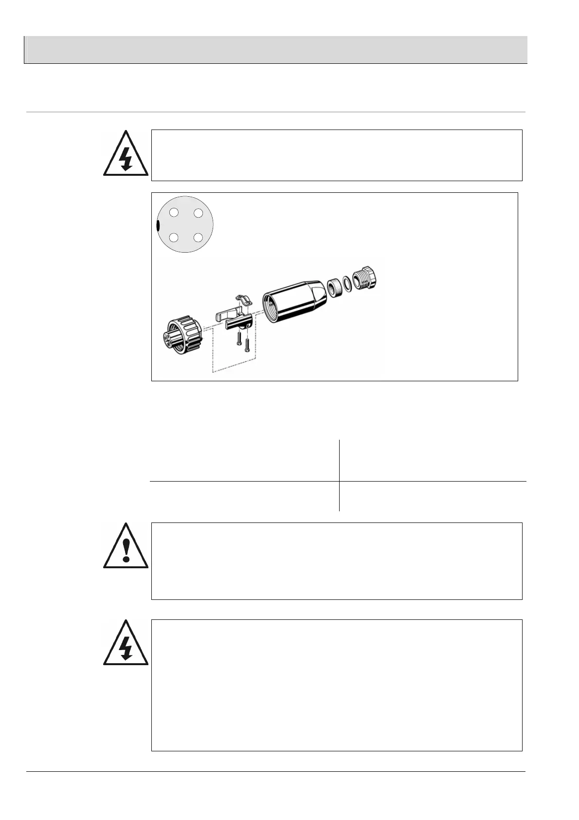
Mains connection
1 - L
2 - N
3 -
4 - PE
2
34
1
Fitting cable coupler
For electrical connection, see section 10.3.
Cable cross-sections
Recommended cable cross-sections between probe connection box
and LT 2/KS1-DK
Probe heater (shielded)
Terminal 35 / 36
Other connecting cables (shielded)
Probe signals
Pressure sensors
up to 20m ≥ 1.5 mm
2
up to 50m ≥ 2.5 mm
2
≥ 0.8 mm
2
Multicable 11 x 0.8 (S-Y(ST)Y..LG)
WARNING
Take care to ensure that cable routing and screening confirms to regulations.
Probe connection:
The signal line of the LT 2/KS1-DK, terminals 12, 33 and 34, must not be routed
together with mains cables, particularly cables of frequency converters for speed
control. Any connection with the power circuit must be avoided.
Lines may be routed together with pressure sensor cables, however.
DANGER
A faulty probe connection may result in the probe being damaged beyond repair.
Before commissioning,
check probe connection terminals 12 to 36
12 (-) Probe signal CO/H
2
33 (-) Probe signal O
2
34 (+) Probe signal CO/H
2
/ O
2
(shared inner electrode)
35 Probe heater
36 Probe heater