10 Appendix
90
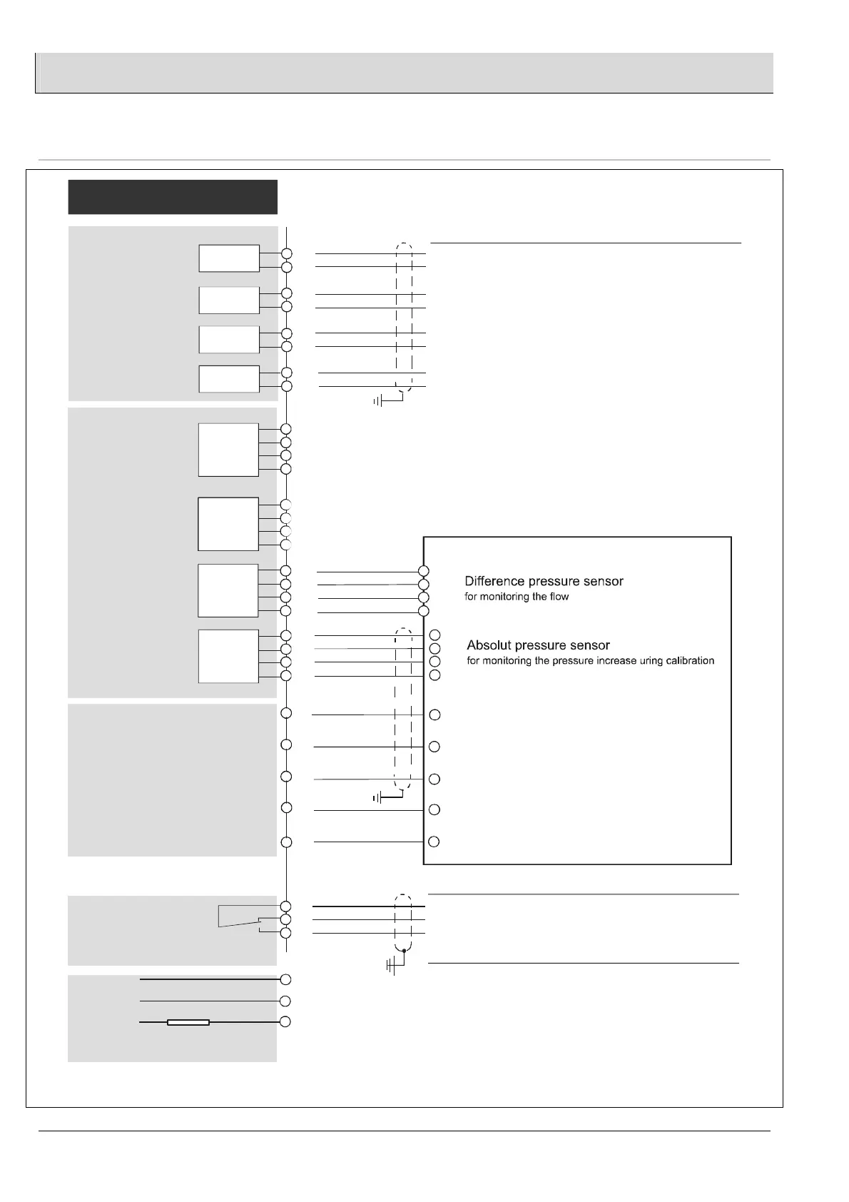
10.3 Electrical connection
(+)
(-)
(+)
(-)
(+)
(-)
(+)
(-)
0/4…20 mA
0/2…10 V
(Option)
* on
processor board
*
Module 4
Analoge
Inputs
Module 1
657P0660
Relay outpt 1
49
48
47
46
45
44
43
42
26
25
24
23
3
2
1
PE
N
L
+
-
/ 250 V [230 V]
/ 250 V [115 V]
Lambda-Transmitter LT 2
Output 4 not connected
Output 3 not connected
Output 2 0...1000ppm COe = 4...20mA
Output 1 0...10% O2 = 4...20mA
0- 42V DC 3A
0-230V AC 2A
F1 T1A
T2A
36
33
34
35
Probe-
connection
KS1-DK
Signal input CO/H2-signal
internal used
12
Sensor heater
sensor heater
CO/H2/O2 sensor signal +
O2 sensor signal -
CO/H2 sensor signal -
26
25
24
23
36
33
34
35
12
sensor heater
sensor heater
CO/H2/O2
sensor signal +
O2 sensor signal -
CO/H2 sensor signal -
Probe Connection Box KS1-DK
diameters
sensor heater
up to 20 m = 1,5 mm
up to 50 m = 2,5 mm
2
2
/
K
S1
-D
K
To be used only in grounded power line networks !
diameters
sensor signals, \
pressure sensors
up to 50 m = 0,8 mm
multi cable J-Y(ST)Y-G
2
18
17
16
15
22
21
20
19
Lambda-Transmitter LT 2
/
K
S1
-D
K
Analoge outputs
*
Module 3
*
Module 2
*
Module 1
Module 2
not
occupied
Module 3
657P0650
difference
pressure
Module 4
657P0650
absolut
pressure
=
Earth
= Neutral conductor
= Phase 230 / 115 V, 48...62 Hz
Line power consumption typically 50 VA
Short-term (probe heating phase) ca. 150 VA
For example, combined fault indication
(configurable as required)
Manufacturer's setting: fault
current principle
22
21
20
19