4 Technical Description
33
4.9 LAMTEC SYSTEM BUS
NOTE:
Data transmission in the LT 2 via the LAMTEC SYSTEM BUS only functions if the
device is set to “MEASUREMENT” and is not in “MAINTENANCE MODE” or
“FAULT”.
When communication is taking place correctly, the two LEDs 1 and 2 flash.
For connecting the field bus module, please see section 10.4
4.9.1 Parameter setting (from software version 1V14)
• P3800 – Value 1 (default)
LAMTEC SYSTEM BUS – Version 1
• P3801 - Devices ID9 (default)
If there is more than one LT in a family, they must have different IDs.
These are set from ID9...ID16.
• P3802 – Device family 1 (default)
All devices that exchange values with one another must be set to the
same family.
• P3803 – O2 OUTPUT VALUE (default)
The LT transmits its O2 value for all devices of the same family.
NO: The LT does not transmit an O2 value for devices of the family.
• P3804 - Transmit CO value for family
NO (default): The LT does not transmit a CO value for devices of the
family.
CO MEASUREMENT VALUE: The LT transmits its CO measurement
value for all devices of the same family.
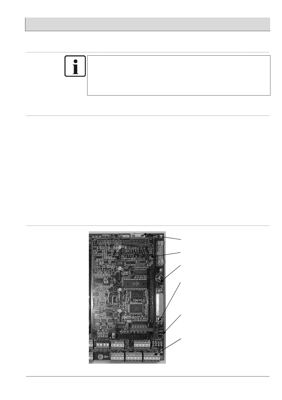
4.9.2 Jumpers, LEDs, fuses and terminals
F6 – T315mA Æ DC5V-LSB
BR12, BR13 Æ setting “C”
BR105 Æ setting 2-3 (clockwise)
LED1 – green Æ RxD of LSB
LED2 – yellow Æ TxD of LSB
BR101 Æ setting 1-2 (clockwise)
Without LSB termination resistor
BR101 Æ setting 2-3 (anti-
clockwise)
With LSB-termination resistor
Term.71 Æ CAN-GND
Term.74 Æ CAN-H
Term.75 Æ CAN-L