8 Fault Analysis/Trouble-shooting
75
8 Fault Analysis/Trouble-shooting
Messages in plain text:
• Via display and operating unit, under “diag”
• Via remote display software (optional extra)
• Indication via LED line, LEDs 7 to 12, on the processor board in the LT 2/KS1-DK
8.1 Fault indicator via LED line in the LT 2/KS1-DK
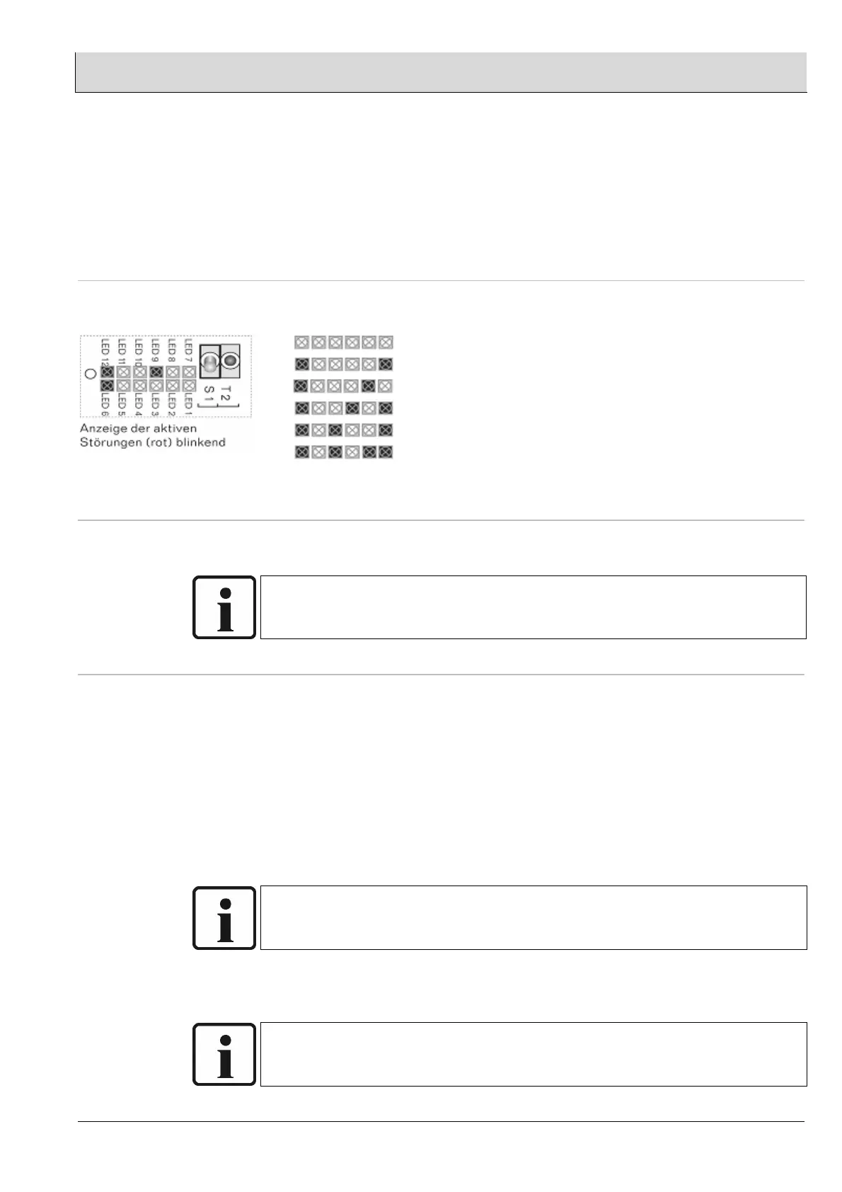
Indication via LED line, LEDs 7 to 12, LED 12 flashes (faults flash)
LED
12 11 10 9 8 7 Faults
No fault active
Probe voltage U-O
2
< -20mV
Faulty probe heater
Probe broken wire/faulty probe
No probe dynamics
Fault in analogue outputs
(1)
– Only relevant when used with integrated O2 control
8.1.1 Probe voltage U-O
2
< -20mV
• Probe + / - reversed polarity → swap probe connection terminals 33-34
• Probe contaminated → replace
NOTE:
Probe voltage U-O
2
in air -20 to +20 mV
8.1.2 Faulty probe heater
• Check fuse F 5 (see section 10.6)
• Inspect the probe heater. If the heater is intact, measure between the two pins of
the probe heater connector (recognisable by the two white wires), approx. 2 ohms
cold, approx. 10 ohms at operating temperature. If this is not the case (infinite
resistance) Æ faulty heater - replace probe.
• If the measurement is successful, check the power supply voltage (with an
effective measuring device or oscilloscope). The probe heater should be supplied
with approx. 13 V DC with cyclical polarity reversal.
• Electromagnetic disturbance through wrong cable routing. Maybe parallel to
frequency converter, actuators, gates.
NOTE:
The probe heater receives power in the form of a direct voltage of approx. 13V, with
cyclical polarity reversal. Measurement with a multimeter is therefore problematic.
• If the above voltage is not received, check the wiring terminal connections and
tighten if necessary.
NOTE:
The current heater data can be read out via the operating data parameters 41/42/43.