6 Commissioning / Shutdown
58
6.1.1 Possible warning / faults
Warning “Internal resistance of probe 1 too high”
Fault “Probe broken wire/faulty probe”
• Trigger of the Warning:
The internal cell resistance has the limit of 200 Ohm exceeded
(in mode “MEASURE”)
• Trigger of the fault:
The internal cell resistance has the limit of 300 Ohm exceeded
(in mode “MEASURE”)
Possible causes:
• Aborting cold start uring heating up phase
• Cable diameter of the probe heating to small
• Probe aged Æ use a replacement probe and exchange it
• Fuse F2 defective
6.2 Setting the cell internal resistance R
I probe
Note the cell internal resistance R
I probe
and read off the probe voltage U-O2 using
these alternatives:
• Display and operating unit
• Remote display software
• Monitor output
When heated to operating temperature (approx. 30 minutes after switch-on), the
measured internal resistance R
I probe
of the O
2
electrode should equal 20 ohms (+/-5
ohms). If the measured internal resistance is higher, increase the power of the probe
heater by 0.5 watts (parameter 180). If it is lower, reduce the heating power by 0.5
watts. Repeat this process until the internal resistance reaches 18 ohms (+/-5 ohms).
Wait approx. 10 minutes before repeating the process, to allow time for the internal
resistance to adapt to the new heating power.
The probe voltage U-O2
stabilises to values between -20...+20mV.
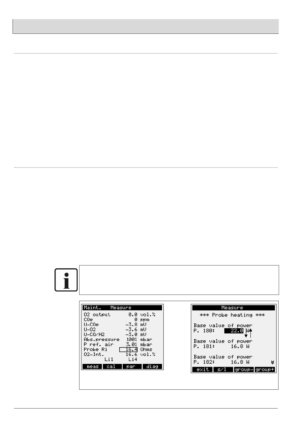
NOTE:
To read off the cell internal resistance R
I probe
and the probe voltage U-O2 → press
“meas”.
LT2 display
P180 is only available in the service level.
If it is not possible to get an internal cell resistance lower then 25 Ohm, check the
cabel diameter aof the probe heating (see chapter 5.2.3).