10 Appendix
91
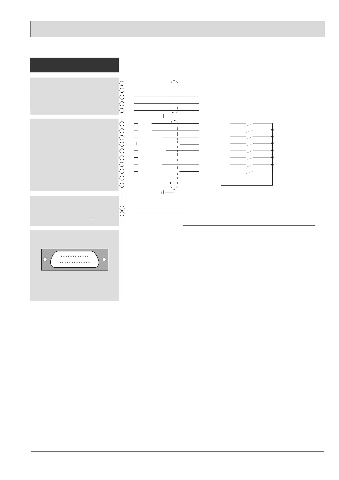
Input 8
GND
LAMTEC SYSTEM BUS
(CAN-BUS)
CAN Low
CAN High
not con.
not con.
CAN-GND
Fuel 4
Fuel 3
Fuel 2 (Gas)
Maintenance ON/OFF
Reference air
Calibration
Reset limits
Reset faults/warnings
75
74
73
72
71
69
68
67
66
65
64
63
62
61
(floating)
LAMTEC SYSTEM BUS
(+)
(-)
32
31
Monitor output
0…2,5 V DC
switch over to O , U (only 0 mV)
2S
>
60
24 V DC
Lambda-Transmitter LT 2
/
K
S1
-D
K
Lambda-Transmitter LT 2
/
K
S1
-D
K
Digital inputs
24 V, ca. 6 mA
Bridge BR 106, BR 107 on
power electronics
1-2 referenced to
(bottom) - instrument potential
2-3 floating potential for
(top) - external voltage source
+24 V
Input 7
Input 6
Input 5
Input 4
Input 3
Input 2
Input 1
For example, for connection of a multimeter
for service purposes Ri > 10 k
Ω
Interface module
Only in conjunction with
remote display software
RS 232
- 6 57 R 1101
RS 422 - 6 63 P 0500
Socket for interface
module, 25 pins