MachXO2 and MachXO3 Starter Kit Evaluation Board User Guide
Evaluation Board User Guide
© 2014-2022 Lattice Semiconductor Corp. All Lattice trademarks, registered trademarks, patents, and disclaimers are as listed at www.latticesemi.com/legal.
All other brand or product names are trademarks or registered trademarks of their respective holders. The specifications and information herein are subject to change without notice.
FPGA-EB-02036-1.4 7
2. Features
The MachXO2 and MachXO3 Starter Kits include:
• Mach XO2/MachXO3L/MachXO3LF Board – The board is a 3” x 3” form factor that features the following on-
board components and circuits:
• One of the following FPGAs
• LCMXO2-4000ZE-1BG256C (Flash Based)
• LCMXO3L-6900C-5BG256C (NVCM Based)
• LCMXO3LF-6900C-5BG256C (Flash Based)
• USB mini-B connector for power and programming
• 4-Mb Serial Flash Memory for boot image and dual-boot support.
• Eight LEDs
• 4-position DIP switch
• Momentary push button switch
• 40-hole prototype area
• Four 2 x 20 expansion header landings for general I/O, JTAG, and external power
• 1 x 8 expansion header landing for JTAG
• 1 x 6 expansion header landing for SPI/I2C
• 3.3 V and 1.2 V supply rails
• Pre-loaded Demo – The kit includes a pre-loaded counter design that highlights use of the embedded
MachXO2 and MachXO3 oscillators and programmable I/O configured for LED drive.
• USB Connector Cable – The board is powered from the USB mini-B socket when connected to a host PC. The
USB channel also provides a programming interface to the MachXO2 and MachXO3 JTAG ports.
• Lattice Development Kits and Boards Web Page – Visit www.latticesemi.com/breakoutboards for the latest
documentation (including this guide) and drivers for the kit.
The content of this user guide includes demo operation, programming instructions, top-level functional descriptions of
the Starter Kit, descriptions of the on-board connectors, and a complete set of schematics.
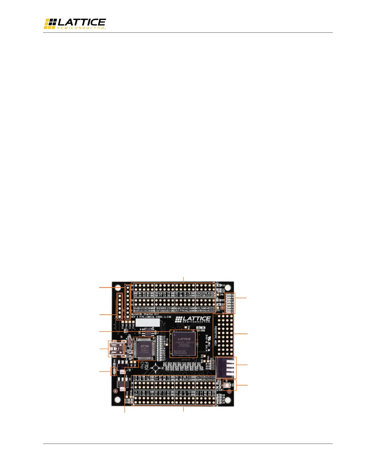
Two 2 x 20 Header
Landings (J3, J4)
Two 2 x 20 Header
Landings (J6, J8)
JTAG Header
Landing (J1)
SPI/I2C Header
Landing (J7)
MachXO3L PLD
(U5)
USB Mini -B
Socket (J2)
Power LED,
Blue (D1)
FTDI USB to
UART/FIFO IC (U1)
Push Button
Switch (SW1)
4-Position DIP
Switch (SW2)
4 x 10 40-Hole
Prototype array
LED array
(D9 -D2)
Figure 2.1. MachXO3 Board (MachXO3L Version), Top Side