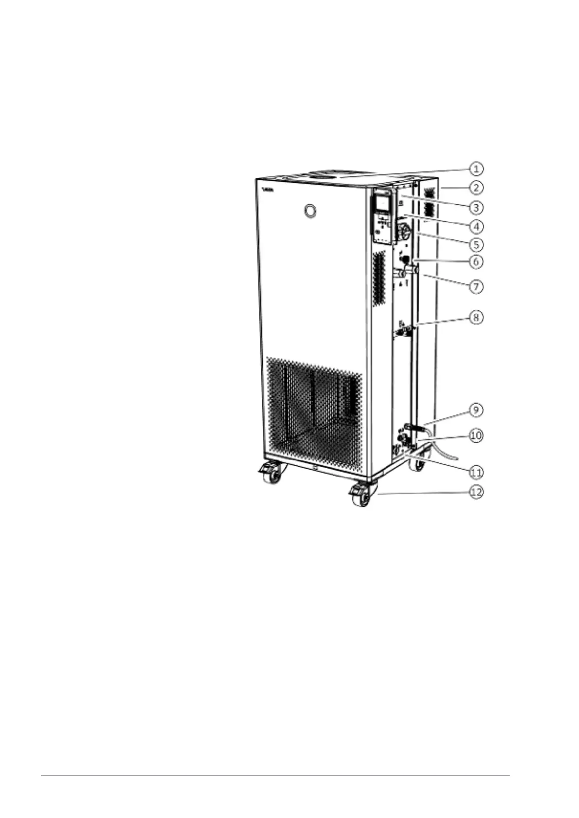
3.2 Overall view of Integral (medium casing version)
Fig. 6: View of Integral 950 XTW
1 Filler nozzle with cover
2 Overflow pipe on the rear of the device (covered)
3 Operating unit
4 Interfaces and two slots for interface module (covered)
5 Mains switch
6 Adjusting wheel for bypass valve
7 Pump connector
8 Drain tap for expansion vessel (from Integral 550 XT)
9 Power cable
10 Drain tap for the hydraulic circuit
11 Connecting sleeve for cooling water (only water-cooled devices)
12 Four castors (front castors with parking brake)
V6Integral Process Thermostats and High-Temperature Thermostats22 / 198