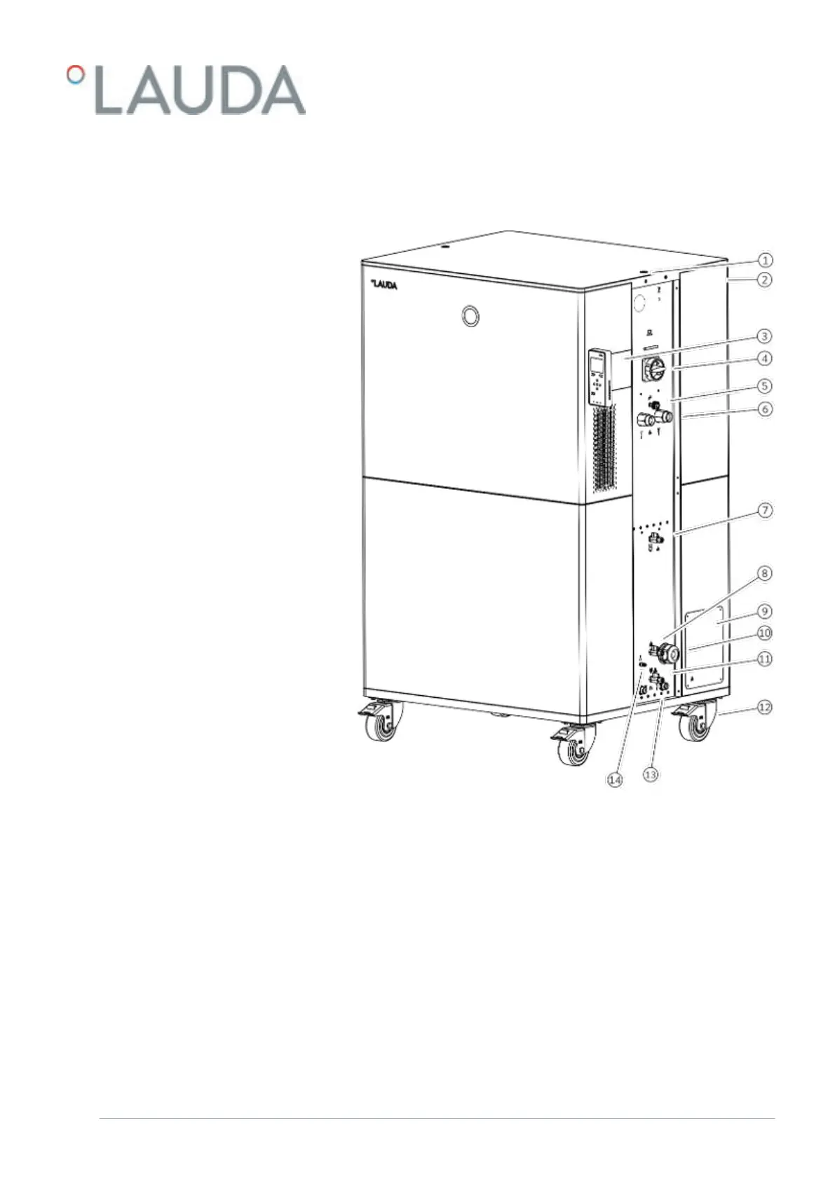
3.3 Overall view of Integral (large casing version)
Fig. 7: View of Integral 2560 XTW
1 Thread connection for ring bolt
2 Overflow pipe on the rear of the device (covered)
3 Operating unit and two slots for interface modules
4 Mains switch
5 Adjusting wheel for bypass valve
6 Pump connector
7 Drain nozzle with drain tap for expansion vessel
8 Filling nozzle with non return valve
9 Connection box for mains cable
10 Cable gland for mains cable inlet
11 Drain nozzle with drain tap for hydraulic circuit
12 Four castors, each with parking brake
13 Connecting sleeve for cooling water
14 Connection for inert gas overlay
V6 Integral Process Thermostats and High-Temperature Thermostats 23 / 198