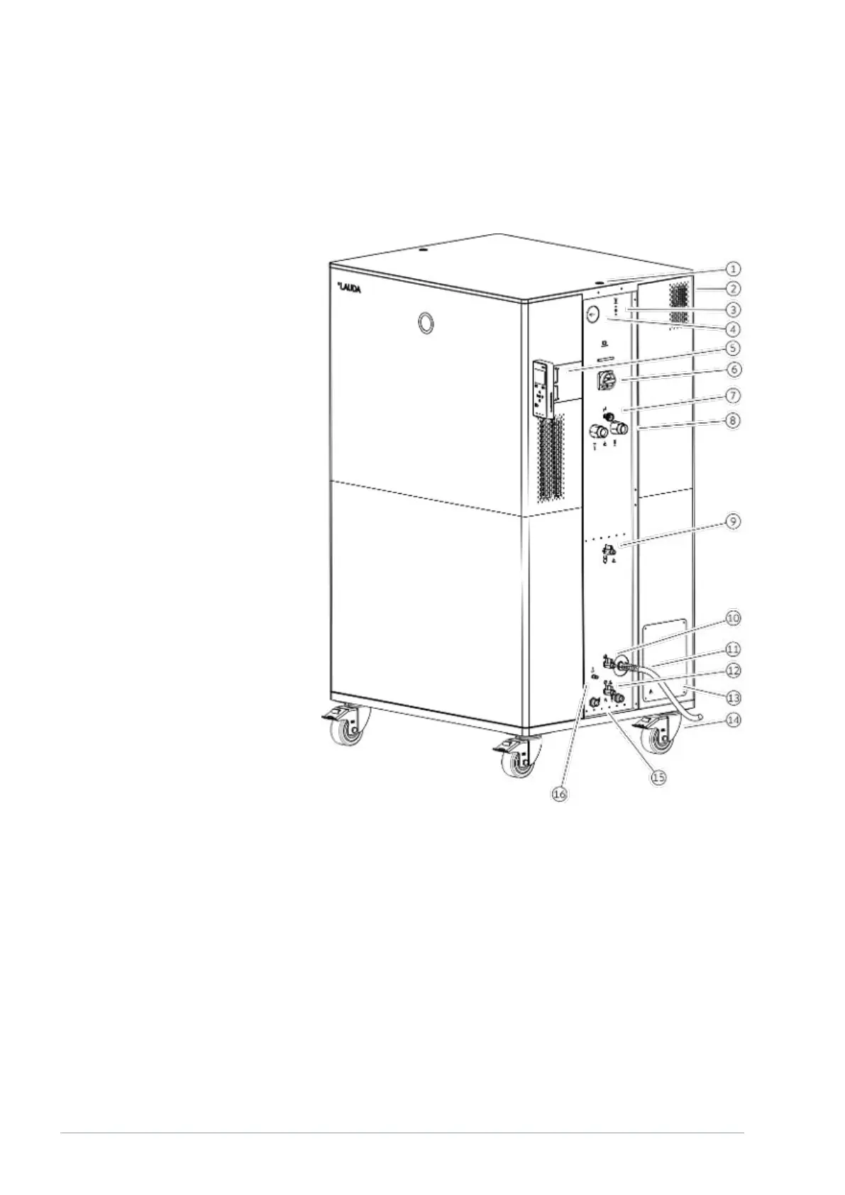
3.4 Overall view of Integral (large casing version) with pressure overlay
Fig. 8: View of Integral 2050 PW
1 Thread connection for ring bolt
2 Overflow pipe on the rear of the device (covered)
3 Pushbutton for releasing the compressed air
4 Hydraulic overpressure indicator (pressure gage)
5 Operating unit and two slots for interface modules
6 Mains switch
7 Adjusting wheel for bypass valve
8 Pump connector
9 Drain nozzle with drain tap for pressure vessel
10 Filling nozzle with non return valve
11 Mains cable
12 Drain nozzle with drain tap for hydraulic circuit
13 Connection box for mains cable (only for 2560 PW)
14 Four castors, each with parking brake
15 Connecting sleeve for cooling water
16 Connection for compressed air
V6Integral Process Thermostats and High-Temperature Thermostats24 / 198