SMC6000 Series Motion Controller Hardware Installation Manual
6
HWMN-SMC6-R20120417
2.1.2. Control Signal Connector J21
Control signal connector provides pulse and direction outputs for position and velocity control. End limit and origin
input are assigned in this connector. See table 2-2 for the detail.
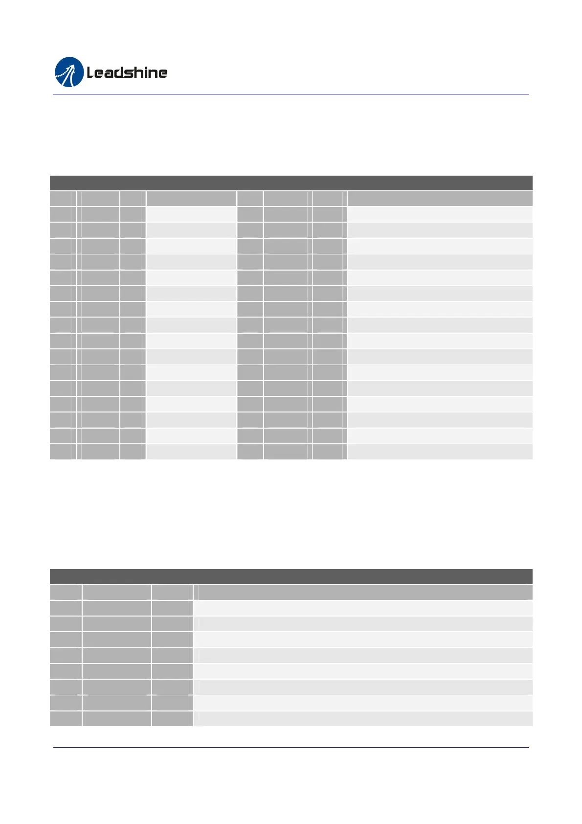
Table 2-2 Control signal connector J21 pin assignment (SMC6480, SMC6490 and PMC6496)
Control Signal Connector Pin Assignment (SMC6480, SMC6490 and PMC6496)
Pin
Signal I/O
Description Pin
Signal I/O Description
1 PUL1+ O Axis 1 Pulse + 17 +5V O +5V Power
2 PUL1- O Axis 1 Pulse - 18 ELx+ I Axis 1 End Limit+, reference to EXGND
3 DIR1+ O Axis 1 Direction + 19 ELx- I Axis 1 End Limit-, reference to EXGND
4 DIR1- O Axis 1 Direction - 20 Ely+ I Axis 2 End Limit+, reference to EXGND
5 PUL2+ O Axis 2 Pulse + 21 Ely- I Axis 2 End Limit-, reference to EXGND
6 PUL2- O Axis 2 Pulse - 22 ELz+ I Axis 3 End Limit+, reference to EXGND
7 DIR2+ O Axis 2 Direction + 23 ELz- I Axis 3 End Limit-, reference to EXGND
8 DIR2- O Axis 2 Direction - 24 Elu+ I Axis 4 End Limit+, reference to EXGND
9 PUL3+ O Axis 3 Pulse + 25 Elu- I Axis 4 End Limit-, reference to EXGND
10 PUL3- O Axis 3 Pulse - 26 ORGx I Axis 1 Origin Input
11 DIR3+ O Axis 3 Direction + 27 ORGy I Axis 2 Origin Input
12 DIR3- O Axis 3 Direction - 28 ORGz I Axis 3 Origin Input
13 PUL4+ O Axis 4 Pulse + 29 ORGu I Axis 4 Origin Input
14 PUL4- O Axis 4 Pulse - 30 EXGND GND
Power Ground
15 DIR4+ O Axis 3 Direction + 31 EXGND GND
Power Ground
16 DIR4- O Axis 3 Direction - 32 EXGND GND
Power Ground
2.1.3. I/O Connector J11
I/O connector J11 provides 16 isolated general purpose digital inputs and 8 isolated general purpose digital outputs.
All digital inputs in this connector can be configured as dedicated or special purpose inputs. See table 2-3 for more
detail.
Table 2-3 I/O Connector J11 pin assignment (SMC6480, SMC6490 and PMC6496)
I/O Connector J11 Pin Assignment(SMC6480, SMC6490 and PMC6496)
Pin Name I/O Description
1
IN1 I* Isolated General-purpose Digital input 1 / Run
2
IN2 I* Isolated General-purpose Digital input 2 / Pause
3
IN3 I* Isolated General-purpose Digital input 3 / Stop
4
IN4 I* Isolated General-purpose Digital input 4 / Home
5
IN5 I* Isolated General-purpose Digital input 5 / X++ (JOG Axis 1 in positive direction)
6
IN6 I* Isolated General-purpose Digital input 6 / X-- (JOG Axis 1 in negative direction)
7
IN7 I* Isolated General-purpose Digital input 7 / Y++((JOG Axis 2 in positive direction)
8
IN8 I* Isolated General-purpose Digital input 8 / Y-- (JOG Axis 2 in negative direction)
Authorized Distributor of Leadshine Technology
www.leadtronker.com
www.leadtronker.com雷赛智能官方代理:雷创智能科技