SMC6000 Series Motion Controller Hardware Installation Manual
11
HWMN-SMC6-R20120417
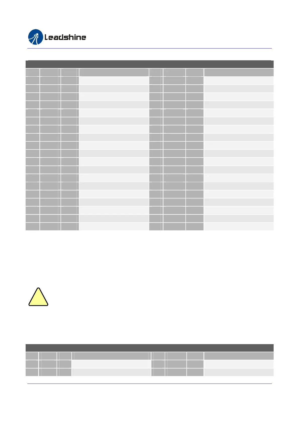
Table2-10 Encoder Connector Pin Assignment (SMC6490 and PMC6496)
Encoder Connector Pin Assignment (SMC6490 and PMC6496)
Pin
Name I/O Description
Pin
Name I/O Description
1
5V O +5V Power Output
20
GND GND 5V Power Ground
2
GND GND 5V Power Ground
21
EA2+ I Axis 2 Encoder Phase A +
3
EA1+ I Axis 1 Encoder Phase A +
22
EA2- I Axis 2 Encoder Phase A -
4
EA1- I Axis 1 Encoder Phase A -
23
EB2+ I Axis 2 Encoder Phase B +
5
EB1+ I Axis 1 Encoder Phase B +
24
EB2- I Axis 2 Encoder Phase B -
6
EB1- I Axis 1Encoder Phase B -
25
EZ2+ I Axis 2 Encoder Index Z +
7
EZ1+ I Axis 1 Encoder Index Z +
26
EZ2- I Axis 2 Encoder Index Z -
8
EZ1- I Axis 1 Encoder Index Z -
27
LTC2+ I Axis 2 Latch Signal Input +
9
LTC1- I Axis 1 Latch Signal Input +
28
LTC2- I Axis 2 Latch Signal Input -
10
5V O +5V Power Output
29
GND GND 5V Power Ground
11
GND GND 5V Power Ground
30
EA4+ I Axis 4 Encoder Phase A +
12
EA3+ I Axis 3 Encoder Phase A +
31
EA4- I Axis 4 Encoder Phase A -
13
EA3- I Axis 3 Encoder Phase A -
32
EB4+ I Axis 4 Encoder Phase B +
14
EB3+ I Axis 3 Encoder Phase B +
33
EB4- I Axis 4 Encoder Phase B -
15
EB3- I Axis 3 Encoder Phase B -
34
LTC1+ I Axis 1 Latch Signal Input +
16
EZ3+ I Axis 3 Encoder Index Z +
35
EZ4- I Axis 4 Encoder Index Z -
17
EZ3- I Axis 3 Encoder Index Z -
36
NC N/A Not Connected
18
EZ4+ I Axis 4 Encoder Index Z +
37
NC N/A Not Connected
19
5V O +5V Power Output
2.1.11. Manual Pulse Connector (SMC6490 and PMC6496)
Manual pulse from the MPG can be used to joy the axes during processing. Leadshine SMC6400B accepts AB phase
input signals. That is, A phase is lead or lag B phase by 90 degree and it represents the move direction. The pulse
frequency can be multiplied by 10 times or 100 times. You need to select which axis to be operated by pulling the
SEL pin to ground before sending the pulse. See table 2-11 for the pin assignments.
Do not connect the GND to EXGND See chapter 2.3 for more information.
Table 2-11 Manual Pulse Connector Pin Assignment (SMC6490 and PMC6496)
Manual Pulse Input Connector Pin Assignment (SMC6490 and PMC6496)
Pin
Name
I/O
Description Pin
Name I/O Description
1
PA I Manual pulse input phase A
9
GND GND
Internal 5V Power Ground
2
PB I Manual pulse input phase B
10
GND GND
Internal 5V Power Ground
!
Caution
Authorized Distributor of Leadshine Technology
www.leadtronker.com
www.leadtronker.com雷赛智能官方代理:雷创智能科技