SMC6000 Series Motion Controller Hardware Installation Manual
13
HWMN-SMC6-R20120417
Chapter 3 Interface Circuit
3.1 Control Signal Output
Leadshine SMC6000 can control 4 axes stepper/servo motor at the same time. By default, the control signal PUL and
DIR of each axis represents pulse and direction signal. They can be configured as CW/CCW signal in the demo
software. See more information in SMC6000’s software manual.
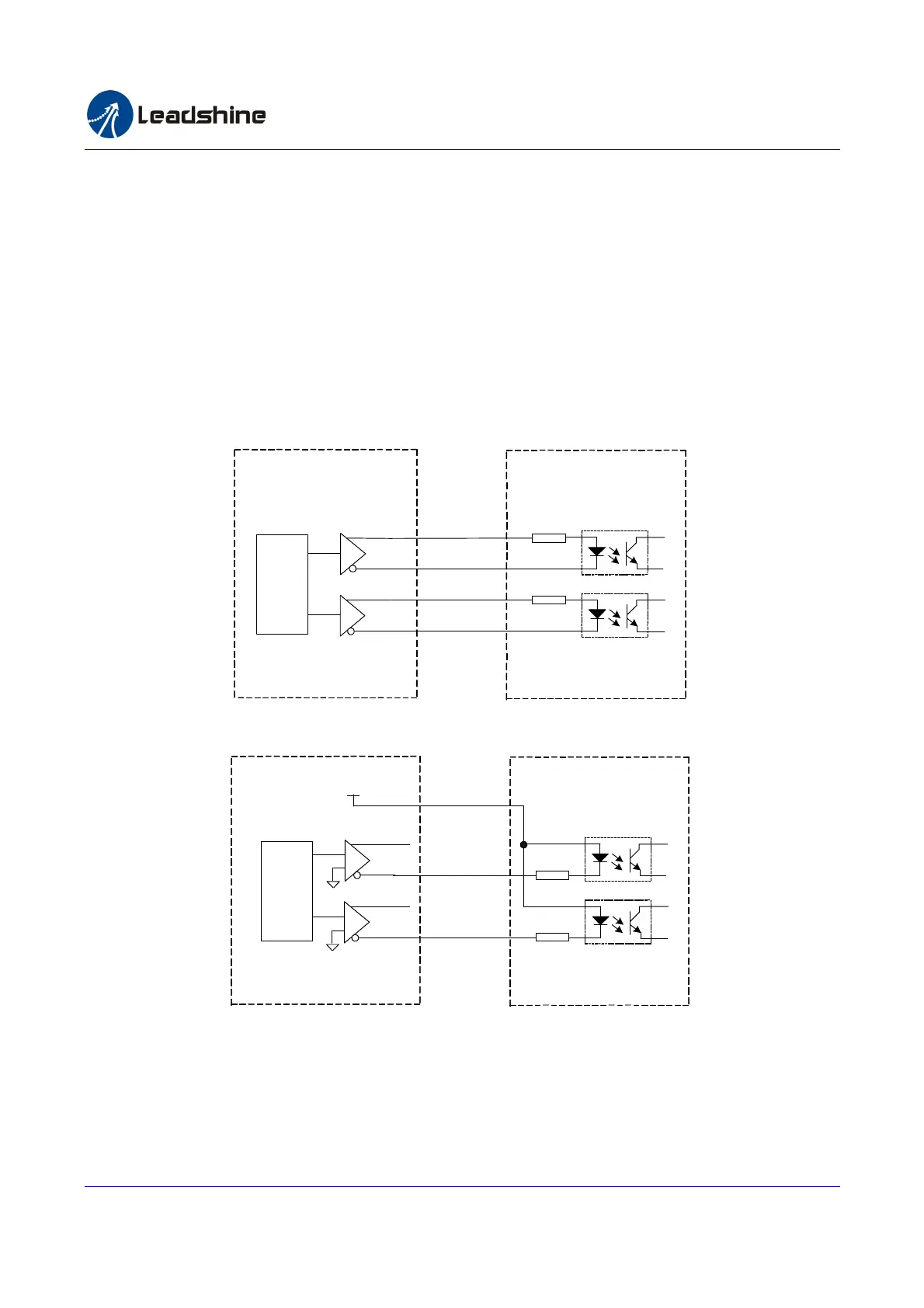
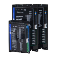
The control signal output circuit and its connection to a differential input stepper drive is shown in figure 3-1. If the
stepper drive is single-ended input, connect it as figure 3-2. Negative output and +5V are used in the single-ended
connections. Please note that the PUL and DIR can only sink/source maximal 20mA which should be enough for the
opto-coupler.
PUL-
DIR-
Stepper Drive
PUL
DIR
R
R
DIR+
PUL+
SMC6000
PUL-
DIR-
DIR+
PUL+
ASIC
Figure 3-1: Differential Output of Control Signal PUL and DIR
PUL
DIR
Stepper Drive
PUL
DIR
R
R
SMC6000
+5V
PUL-
DIR-
DIR+
PUL+
ASIC
OPTO
Figure 3-2: Single-ended Output of Control Signal PUL and DIR
3.2 Origin Input ORG
ORG signal is used to detect the mechanical home/origin position in a machine. SMC6000’s ORG input circuit is
shown in figure 3-3. The built-in opto-coupler and low-pass filter prevent electronic interference from coupling into
the motion controller thus increase system reliability. See table 2-2 for pin assignment of ORG signal in the
Authorized Distributor of Leadshine Technology
www.leadtronker.com
www.leadtronker.com雷赛智能官方代理:雷创智能科技