SMC6000 Series Motion Controller Hardware Installation Manual
10
HWMN-SMC6-R20120417
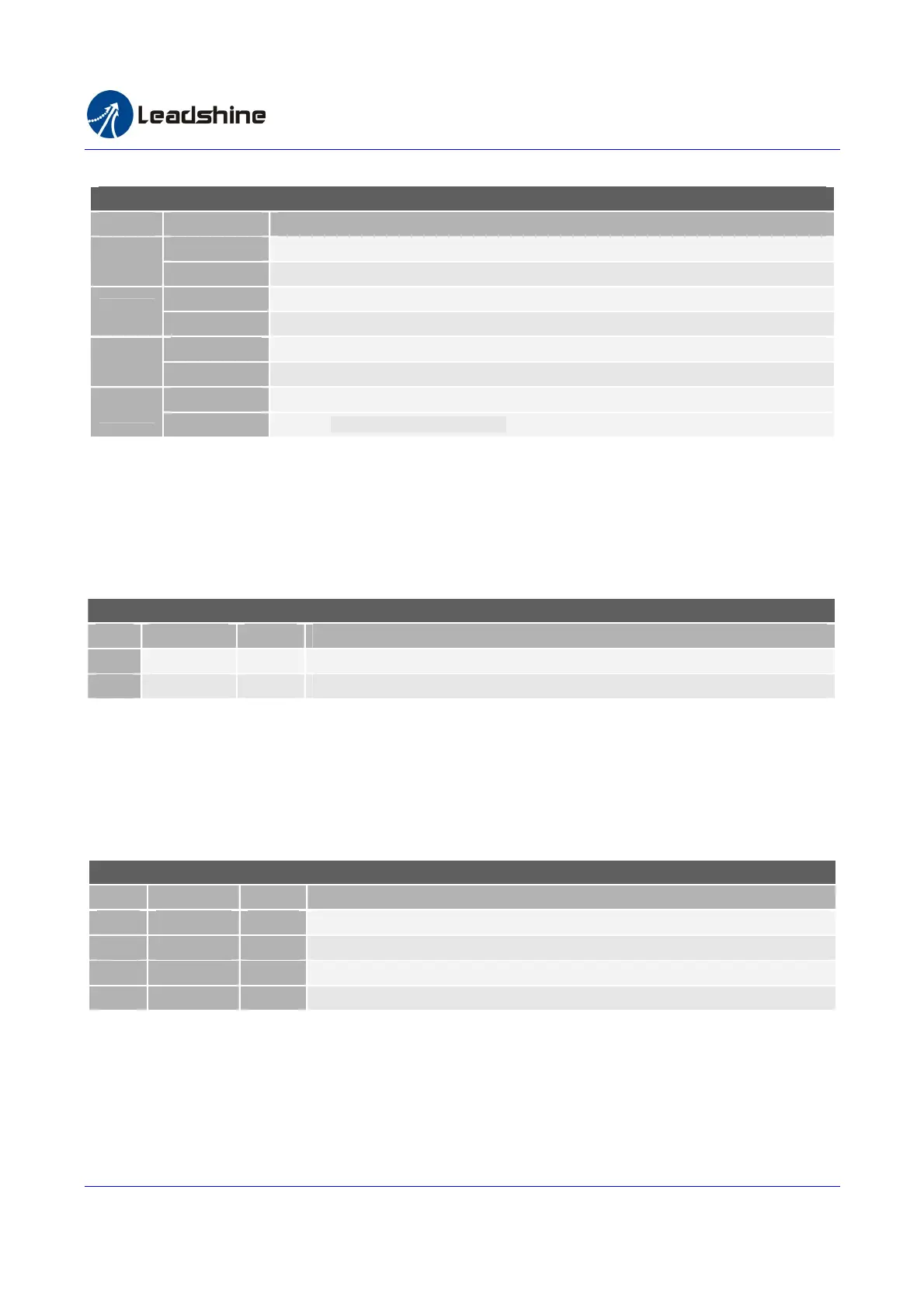
Table 2-7 DIP Switch Function (SMC6480, SMC6490 and PMC6496)
Power-up Level DIP Switch Function (SMC6480, SMC6490 and PMC6496)
SWITCH
ON/OFF Description
ON Power-up level of digital outputs 17-24 is 0
1
OFF Power-up level of digital outputs 17-24 is 1
ON Power-up level of digital outputs 9-16 is 0
2
OFF Power-up level of digital outputs 9-16 is 1
ON Power-up level of digital outputs 5-8 is 0
3
OFF Power-up level of digital outputs 5-8 is 1
ON Power-up level of digital outputs 1-4 is 0
4
OFF Power-up level of digital outputs 1-4 is 1
2.1.8. E-Stop Connector (SMC6480)
When the E-Stop input is activated, all the axes will stop and no pulse output. See table 2-8 for the pin assignment.
Figure 3-5 illustrates how to connect an E-step switch to the controller.
Table 2-8 E-Stop Connector Pin Assignment (SMC6480)
E-Stop Connector Pin Assignment (SMC6480)
Pin Name I/O Description
1
EMG I E-stop Input
2
EXGND GND External power ground.
2.1.9. D/A Output Connector (SMC6480)
The D/A output is reference to AGND. Its swing rang is from 0.07-4.45V. The output circuit is shown in figure 3-18.
See the pin assignment in table 2-9.
Table2-9 D/A Output Connector Pin Assignment (SMC6480)
D/A Output Connector Pin Assignment
Pin
Name I/O Description
1
Analog A O D/A output channel A
2
Analog B O D/A output channel B
3
AGND GND D/A output ground
4
AGND GND D/A output ground
2.1.10. Encoder Connector(SMC6490 and PMC6496)
The encoder input can be used for pulse counting of position feedback. There are up to 4 channel AB phase and Z
index inputs with latched signal for capture of position. All of the inputs are TTL compatible
Authorized Distributor of Leadshine Technology
www.leadtronker.com
www.leadtronker.com雷赛智能官方代理:雷创智能科技