MPC2810 Motion Controller Hardware Manual
22
3.2 Signal Interface
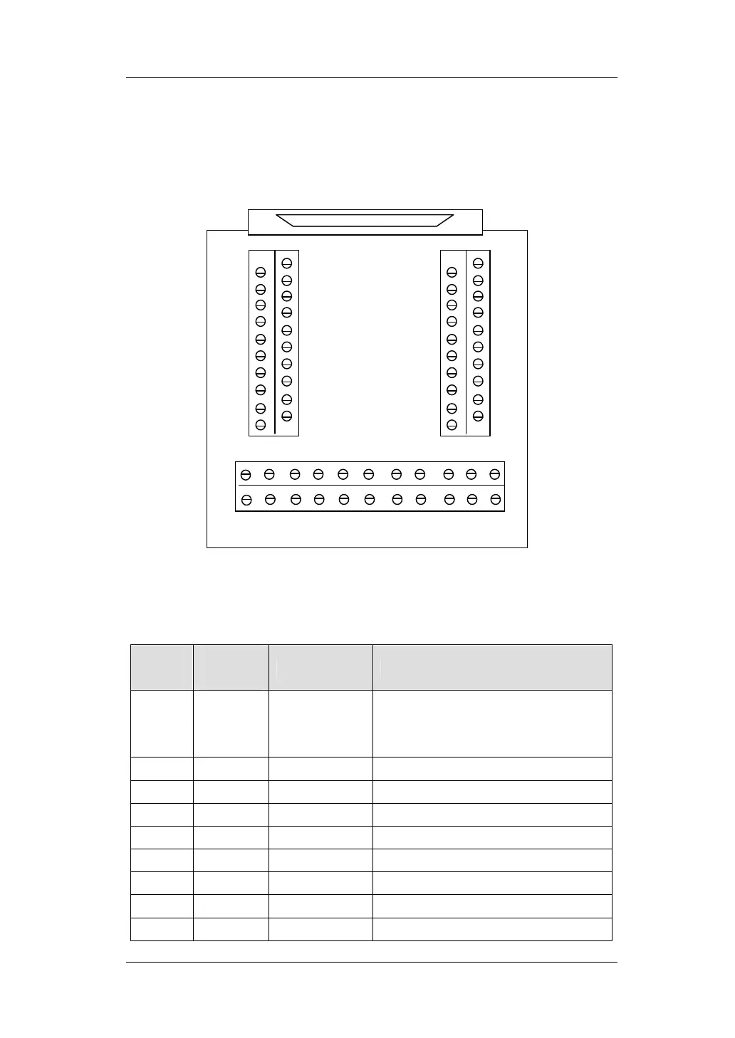
3.2.1 Breakout board-P62-01
Fig. 3-2 P62-01 Breakout board Layout Diagram
Table 3-2 Breakout board Interface Description
P62-01
62-pin
cable
Name Description
D1 42 DCV5V
+5V output(max current:500mA), common
ground with DCV24V, can be
disconnected
D2 21 DCV24V
+24V, input (Compulsory)
D3 20 OGND
24V GND, input (Compulsory)
D4 62 SD1 Axis-1 Ramp-down Signal
D5 41 EL1- Axis-1 Reverse Limit Signal
D6 19 EL1+ Axis-1 Forward Limit Signal
D7 61 ORG1 Axis-1 Homing Signal
D8 40 SD2 Axis-2 Ramp-down Signal
D9 18 EL2- Axis-2 Reverse Limit Signal
D61
D59
D57
D55
D53
D51
D49
D47
D45
D43
D62
D60
D58
D56
D54
D52
D50
D48
D46
D44
D1
D2
D3
D4
D5
D6
D7
D8
D9
D10
D11
D12
D13
D14
D15
D16
D17
D18
D19
D20
D41 D39 D37 D35 D33 D31 D29 D27 D25 D23 D21
D42 D40 D38 D36 D34 D32 D30 D28 D26 D24 D22