MPC2810 Motion Controller Hardware Manual
32
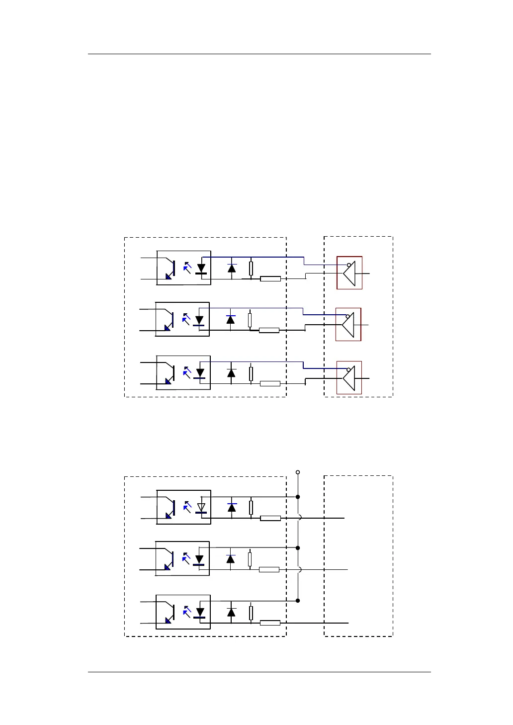
3.3.3.2 Connect Encoder Inputs
2-CH encoder interfaces receiving A-phase, B-phase and Z-phase signals are
available. D28, D29 (axis-1) and D34, D35 (axis-2) function as the differential
ports for encoder latching inputs once the encoder latching functionality
activated. Please refer to Fig.3-10, the connection diagram. Fig. 3-11 shows the
connection example provided encoder latch signals are single-ended.
Up/down pulse mode: Connect external pulse signal to the pulse input port of
corresponding A-phase, and the external direction signal to pulse input port of
corresponding B-phase.
26LS31
26LS31
26LS31
MPC2810 Encoder
Fig. 3-10 Connection Diagram of Encoder Inputs (Differential)
EA+
EA-
EB+
EB-
EZ+
EZ-
D25
D24
D27
D26
D29
D28
+5V
MPC2810 Encoder
Fig.3-11 Connection Diagram of Encoder Inputs(Single-ended)
EA
D25
D24
D27
D26
D29
D28
EB
EZ