MPC2810 Motion Controller Hardware Manual
30
3.3.2 Connect P2810 to Power Supply
Connect D2 and D3 of P62-01 to a 24V switching power supply (D2 to
+24V, D3 to 24V GND).
3.3.3 Connect P62-01 to Motor Drive
3.3.3.1 Outputs
Two pulse output modes for MPC2810: Pul/Dir, and CW/CCW. Default mode is
Pul/Dir. User can change the output mode of each axis using “set_outmode”
command. (Refer to Programming Manual).
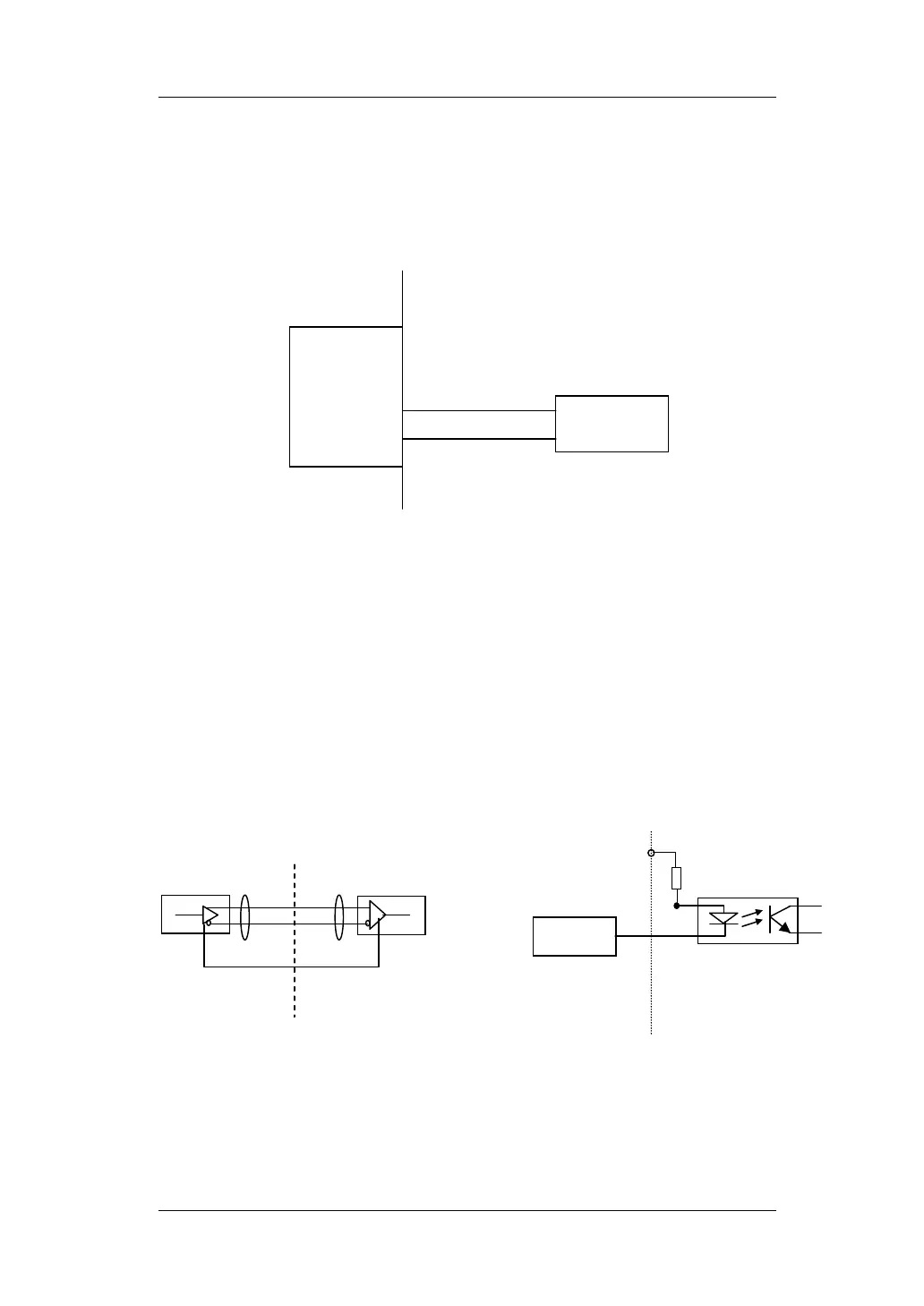
Fig. 3-5 Connect Breakout Board to Power Supply
P62-01
+
-
DC24V
D2
D3
Fig. 3-6 Wiring of Controlling Signals
Equivalent Circuit
MPC2810 Motor Drive
(a) Connect to Differential Signals
MPC2810 Motor Drive
(b) Connect to Single-ended Signals
+ +
GND