MPC2810 Motion Controller Hardware Manual
29
SD1 Axis-1 Ramp-down SD2 Axis-2 Ramp-down
Table 3-10 Connectors AXIS3、AXIS4 Description
AXIS3 pin #
Description
AXIS4 pin #
Description
D3+ Axis-3 direction+ D4+ Axis-4 direction+
D3- Axis-3 direction- D4- Axis-4 direction-
P3+ Axis-3 pulse+ P4+ Axis-4 pulse+
P3- Axis-3 pulse- P4- Axis-4 pulse-
DC5V +5V output (reserve) DC5V +5V output (reserve)
E3+ Axis-3 Forward Limit E4+ Axis-4 Forward Limit
E3- Axis-3 Reverse Limit E4- Axis-4 Reverse Limit
ORG3 Axis-3 Homing ORG4 Axis-4 Homing
SD3 Axis-3 Ramp-down SD4 Axis-4 Ramp-down
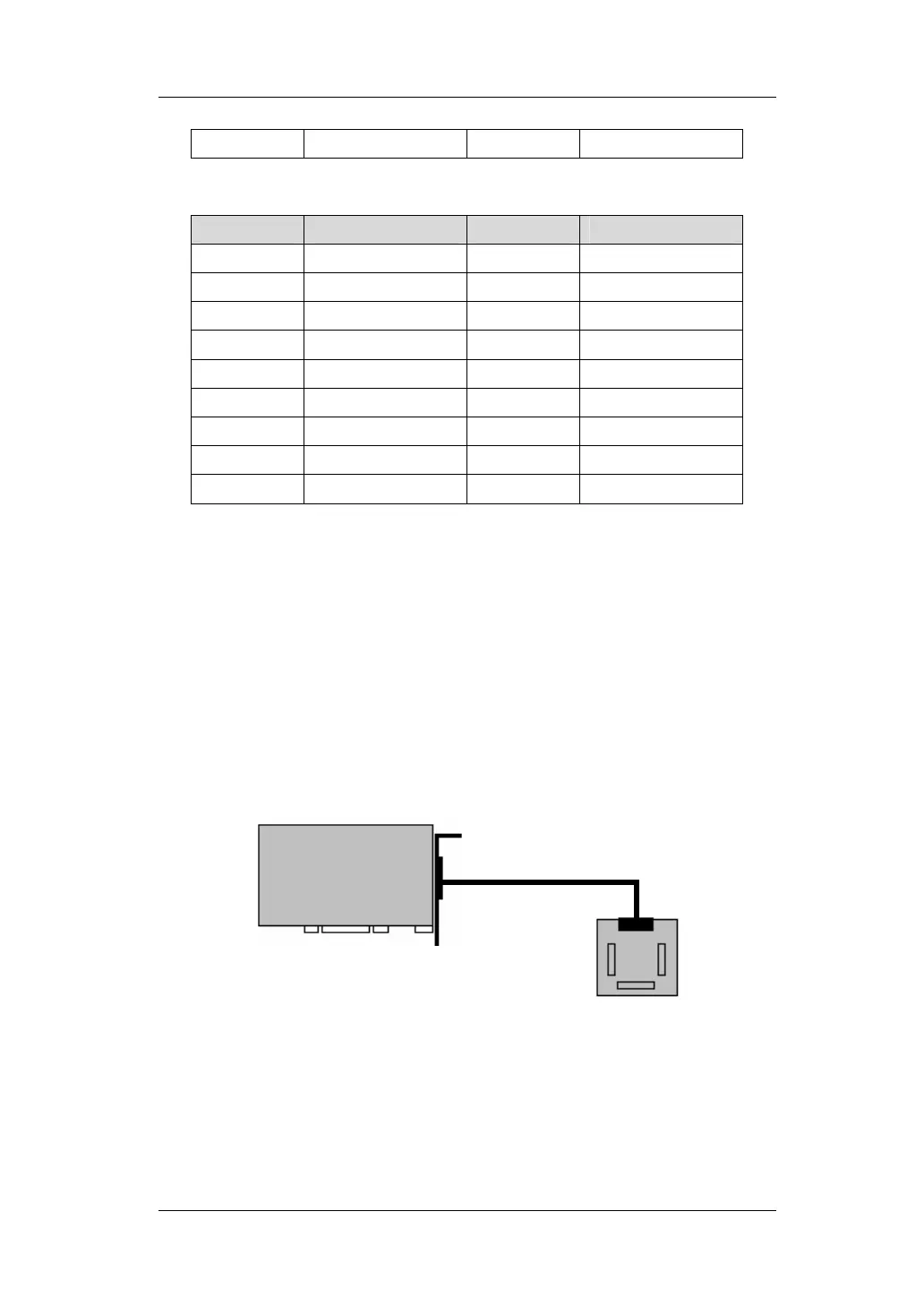
3.3 Connection
3.3.1 Connect MPC2810 to P62-01
Power off the PC
Plug MPC2810 into the PCI-slot of the PC
Connect JP1 interface of MPC2810 to J1 interface of P62-01 with
the 62-pin shielded cable as shown in figure 3-3:
JP1
MPC2810
Shielded cable
P62-01
Fig. 3-4 Connect Motion Control Card to Breakout Board
J1