26
Display Description Press
Point to the desired
Panel IR Sensor and
press ‘Select’
Point the LMCT-100 at the infrared sensor on the
LMRD board and press Select.
One of the following screens will display,
depending on the Status option you selected.
lect
Panel Status
This screen displays the date and time,based on the panel settings, sunrise/sunset times based on date and location settings, whether
the current date is a holiday, and the current settings of the dip switches. Additionally, it will display an error message for certain
problems.
Display Description Press
15:19 STD Non-Holiday
Sunrise: 06:14
Sunset: 16:47
Con LEDs: 00000000
Dip Switch: 00000000
Panel Status
Nov 10, 2014 Mon
DONE
Most fields on this screen are self explanatory. A
value of “STD” indicates standard time and a value
of “DST” indicates daylight savings time
For the Dip Switch field, a value of 1 indicates that
particular dip switch is set to ON. For details on
what each dip switch controls, see “Dip Switches”
on page <?>.
The Con LEDs field indicates errors, and will show
“1” in individual digits when the Config LED is lit
solid and not blinking. From left to right, the error
categories are as follows:
• 1st and 2nd digits – not used
• 3rd digit – RTCLOCK
• 4th digit – SEEPROM
• 5th digit – Bootload
• 6th digit – Power
• 7th digit – DLM Local Network
• 8th digit – Relay
Press Select to return to the Status screen.
lect DONE
Load Status
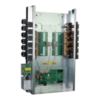
This set of screens displays details about each load in the panel, as well as any loads in connected room controllers.
Display Description Press
Load 1 Status
Load On: Select More
01 1 1 11111111 10
11 1101101001 20
21 11101. . . . . 30
31 . . . . . . . . . . 40
41 . . . . . . . . . . 50
51 . . . . . . . . . . 60
The first screen indicates the on/off status of each
load. A value of “1” indicates it is ON. A value of “0”
indicates it is OFF. A value of “.” indicates no load
exists for that number.
The loads within the panel display first followed
by loads from connected room controllers. In the
example to the left, loads 1–24 are within the panel
and load 25 is from an LMRC-101.
For additional details about the load, highlight that
load and press Select to open the Load x Online
screen. (If you try and select a number for which
there is no load, nothing happens.)
To return to the Status screen, scroll down past
the bottom row (51–60). A second screen displays
showing loads 21–64. Highlight DONE and press
Select.
then press
Select
or
to select the
desired load
1 2 3 4 5 6
. . . . . .
7 8 9 10 11 12
. 1 . . . .
13 14 15 16
. . . .
Load 1 Online
PROPERTIES DONE
This screen displays the BACnet priority of the load
DLM devices will typically have a priority of 8.
Highlight PROPERTIES and press Select.
lect
The “1” indicates
a priority of 8.
 Loading...