680 Series Video Distribution Amplifiers Installation and Operation Manual 9
Chapter 2: UDA-683 Utility Video Distribution Amplifier Modules
Configuration
AC Coupling
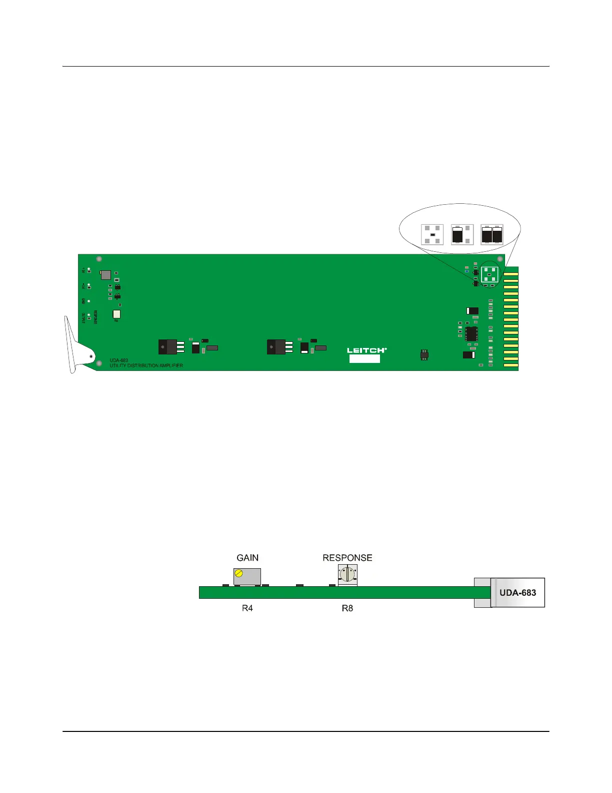
If AC coupling is required, the 0Ω resistor (R19) must be removed and the
optional 22μF/16V(SMT 7343) input coupling capacitors (C18 and C20) must
be installed. This is shown in Figure 2-3.
Figure 2-3. Configuring the UDA-683 for AC Coupling
Operation
Two potentiometers are located at the front edge of the module: GAIN and
RESPONSE
• The multi-turn GAIN potentiometer provides adjustment of over a range of
–3 to +6 dB. The gain is increased when this pot is adjusted clockwise.
• The single-turn RESPONSE potentiometer allows fine adjustment of the
frequency response. It has been factory-set/calibrated; readjusting is not
recommended without precise test equipment.
Figure 2-4. Gain and Frequency Response Adjustments
GAIN
B
C
D
E
F
H
J
K
L
M
N
P
R
S
P1
R19
C18 C20
AC Coupling
R19 R19
C18 C18 C18C20 C20 C20
1. Remove R19 2. Install C18 3. Install C20