680 Series Video Distribution Amplifiers Installation and Operation Manual 25
Chapter 6: VPD-683-CLP Programmable Video Distribution Amplifier Modules
Configuration
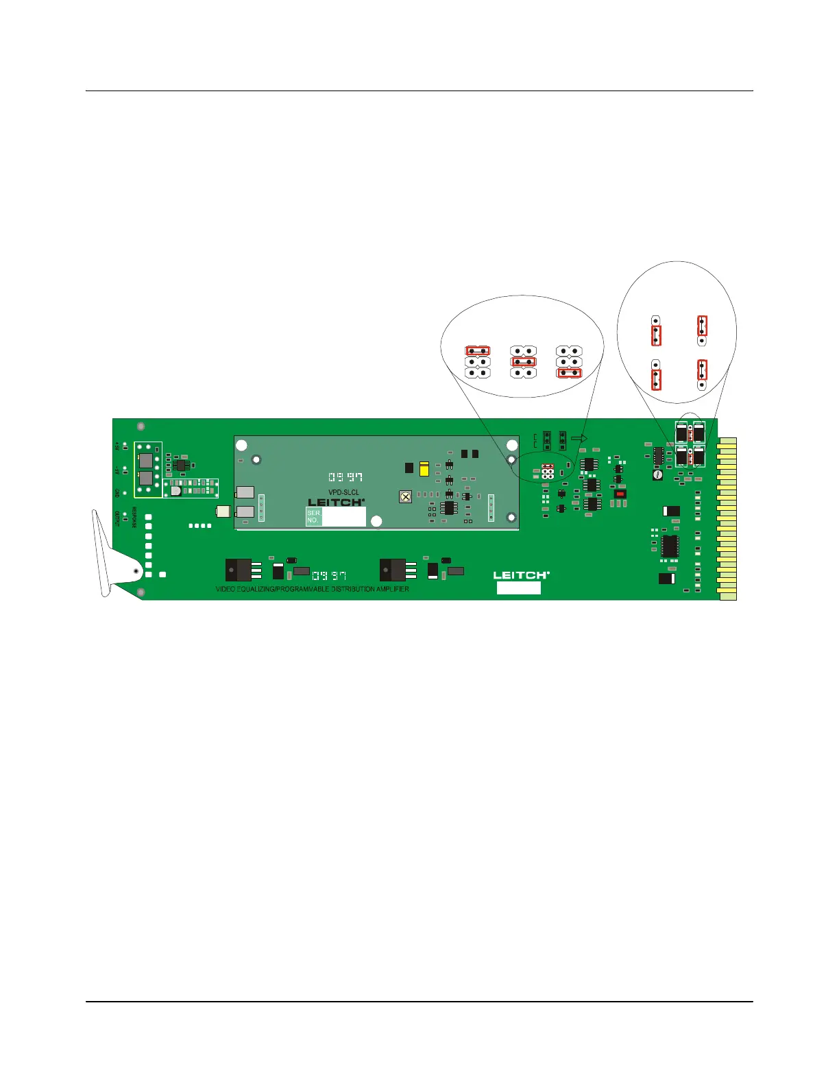
1. Set the input coupling for either AC or DC coupling on Jumpers J1 and J2
(see Figure 6-3).
2. Set the clamping mode on Jumper J3 to either Soft Clamp, Hard Clamp, or
No Clamp (see Figure 6-3).
.
Figure 6-3. VPD-683-CLP Location of Jumpers
3. A multi-turn potentiometer, R5 on the base module, allows for adjustments
to the gain over a range of –3 dB to +3 dB. This gain is increased when this
potentiometer is adjusted clockwise (see Figure 6-4 on page 26).
4. Another multi-turn potentiometer, R6 on the base module, allows for
adjustments to the equalization. It is adjusted clockwise to obtain more
equalization (see Figure 6-4 on page 26).
5. A single-turn potentiometer, R21 on the base module, allows for fine
adjustments to the high frequency response. It has been factory-set/
calibrated; readjusting is not recommended without precise test equipment
(see Figure 6-4 on page 26).
6. The Hard Clip level can be adjusted with the multi-turn potentiometer, R4,
located on the VPD-683-CLP submodule (see Figure 6-4 on page 26).
7. The Luminance Clip level can be adjusted with the multi-turn
potentiometer, R13, located on the card edge of the submodule card (see
Figure 6-4 on page 26).
B
C
D
E
F
H
J
K
L
M
N
P
R
S
VEA-684
VPD-683-D
VPD-683-XEQ
VPD-683-CLP
VPD-683-DEQ
-RMV
-
1
2
3
4
P3
R38
1
2
3
4
P4
R36
CLAMP MODE FOR J1
INPUT COUPLING SETTING FOR J2 AND J3
AC
33
22
J2 J3
11
DC
NO CLAMP
HARD
SOFT
GAIN EQ
VEA-684-RMV
J2
J3
J3 J3J3
SOFTHARD
DC AC
NO
CLAMP
J3 J3
J2 J2
Clamp Mode
Input Coupling
1
2
3
4
P3
R38
1
2
3
4
P4
R36
HARD CLIP
LUM CLIP
1
2
3
4
P1
1
2
3
4
P2