Measuring
31
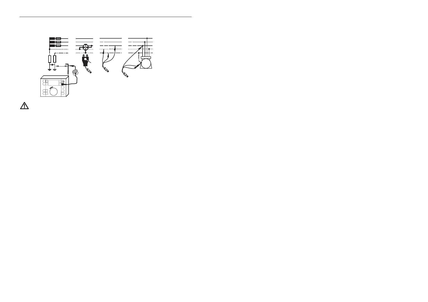
Measuring process:
L
1
= brown
L
2
= black
L
3
= purple
Instrument
Marker
L3
L1
L2
L
2
L
1
L
3
N
P
E
(PEN)
L3
L1
L2
Instrument
Instrument
M
Connection for use with a probe
Probe
RA
R
B
> 20m
R
A
Observe overload capacity and connect instrument as shown.
Note: By measurements on earthing/grounding systems which were
connected with the mains-power-system, e.g. through bonding leads (short
circuit leads) between PE and N-wire, this connection must be interrupted
during the measurement. In the other case the loop-internal resistance will be
measured!
Turn central selector in position R
A
to desired range.
This automatically brings up the applied mains voltage into the display (see also
section 3.6).
Pressing key
S „Display“ also allows a call-up of the noise voltage „U
S-PE
“
between PE connection and probe.
For triggering press measurement key
R „Start“.
Now a range-dependent test current (max. 1 A) is placed across the earth/ground-
connection and earth/ground, and the voltage drop with respect to the sonde is
measured.
On completion of the measurement, the earthing/grounding-resistance R
A
is
displayed. In case of unfavorable resolution or overrange, turn the central selector
to a suitable range and repeat the measurement.
For another measurement press key R „Start“ again.
To return to the original measuring mode for display of the mains voltage U
L-PE
,
briefly turn the central selector.
ATTENTION! To avoid spurious influences, the probe must be set outside any
voltage funnels. Therefore a distance of approx. 20 m must be kept from all
effective earth/ground connections.
To check for this, perform a measurement, remembering the measured value.
Reposition probe and repeat measurement. If the measured value remains
unchanged, the distance of the probe from the earth/ground connections is