Measuring
33
3.9 Loop Resistance (R
LOOP
)/Earthing/Grounding Voltage
The measuring mode „R
LOOP
“ serves to check the protective measures „Zeroing“
and „Earth/Ground-Connection“, in TN and TT networks, under DIN VDE 0100 and
ÖVE-EN1. This permits rapid measurement of the loop resistance between L and
PE and the internal mains resistance between L and N up to 200 Ohm in networks
from 101 to 435 V. These measurements can also be effected between 2 phases
(e.g. L1, L2). In addition it is possible to display the short-circuit current I
K
and the
current nominal voltage to which I
K
refers. The correct polarity with respect to the
mains is automatically set by the instrument if L and N have been exchanged.
For measuring the earthing/grounding voltage (U
S-PE
), the voltage between PE and
probe if the measured short-circuit current flows, a probe may be connected.
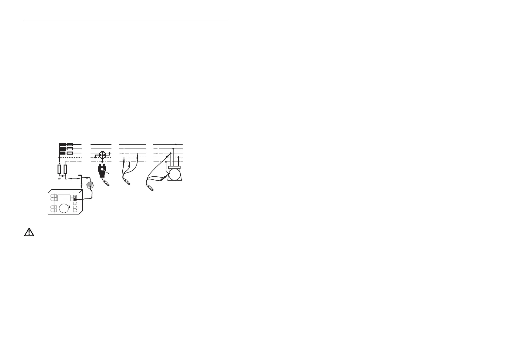
Measuring Process
R
B
> 20m
L
1
= brown
L
2
= black
L
3
= purple
Instrument
Marker
L3
L1
L2
L
2
L
1
L
3
N
P
E
(PEN)
L3
L1
L2
M
Connection for use with a Probe
Probe
R
A
Instrument
Instrument
R
LOOP
Observe overload capacity and connect instrument as shown.
Turn central selector in mode R
LOOP
to desired position L-N for internal resistance
or L-PE for loop Resistance. When using the 3-pole measuring lead, this switching
may only be used if all 3 cables are wired correctly! Now the mains voltage is
displayed dependent on the switch position L-N or L-PE (see also section 3.6).
Press key „Start“.
Press key
R „Start“.
Read measured value.
After pressing key
S „Display“, the pertinent short-circuit current (I
K
) is displayed;
another press yields the nominal voltage (U
N
) and in case of use of a sonde, the
earthing/grounding voltage „U
S-PE
“.
For another measurement press key „Start“ again.