Page 42
C-Determining Unit CFM - Multi-Stage, Direct Drive
Blowers
1- Refer to multi-stage direct drive blower tables, the
measured static pressure, and the factory-set blower
speed to determine CFM.
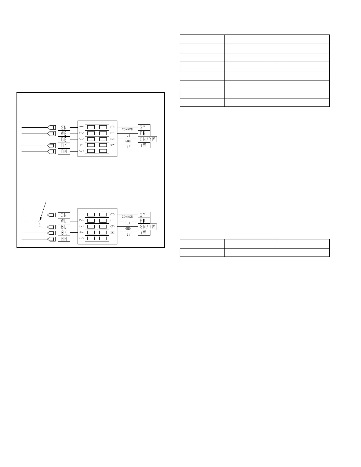
2- If CFM is lower than the design specified CFM, move
the leads as shown in figure 10 for 208/230 volt single
phase units.
DIRECT DRIVE BLOWER LEADS
1 PHASE
B3-W1
B3-G
B3-Y1
B3-W2
B3-W1
B3-G
B3-Y1
B3-W2
DEFAULT
Line Voltage24VAC
INCREASE SPEED
To increase the speed, move the
lead labeled B3-W1 from the white
(WE) wire to the blue (BE) wire.
Note - Operating units using other wire
connections in heating mode may result in
operation outside of this unit's FER rating.
FIGURE 10
D-Determining Unit CFM - Belt Drive Blowers
IMPORTANT - KGB074, 090S4T blower (G thermostat)
CFM MUST BE ADJUSTED IN HIGH SPEED. Discon
nect factory-installed J350 low speed connector from
P350. Connectors are located near the bottom of the
control box. Connect J351 high speed connector to
P350. Once blower CFM is set, J350 can be reconnect
ed to operate the blower on low during ventilation only
demands. See table 4.
1- The following measurements must be made with air fil
ters in place.
2- With all access panels in place, measure static pres
sure external to unit (from supply to return). Blower per
formance data is based on static pressure readings
taken in locations shown in figure 7.
Note - Static pressure readings can vary if not taken where
shown.
TABLE 4
TWO-SPEED BLOWER OPERATION
KGB074, 090S4T UNITS
Thermostat Blower Speed
G (P350/J350)* Low
G (P350/J351) High
W1 High
W2 High
Y1 Low
Y2 High
Dehum High
*Factory-installed jack/plug connection.
3- Measure the indoor blower wheel RPM.
4- Referring to belt drive blower tables, use static pres
sure and RPM readings to determine unit CFM. Use
the air resistance tables when installing units with any
of the options or accessories listed.
5- The blower RPM can be adjusted at the motor pulley.
Loosen Allen screw and turn adjustable pulley clock
wise to increase CFM. Turn counterclockwise to de
crease CFM. See figure 11 Do not exceed minimum
and maximum number of pulley turns as shown in table
5.
6- KGB074S4T and 090S4T Unit Only -
If low speed during ventilation is desired, replace J351
connector with J350.
TABLE 5
MINIMUM AND MAXIMUM PULLEY ADJUSTMENT
Belt Min. Turns Open Maxi. Turns Open
A Section No minimum 5
E-Blower Belt Adjustment
Maximum life and wear can be obtained from belts only if
proper pulley alignment and belt tension are main
tained. Tension new belts after a 24-48 hour period of op
eration. This will allow belt to stretch and seat grooves.
Make sure blower and motor pulley are aligned as shown in
figure 12.
1- Loosen four bolts securing motor base to mounting
frame. See figure 11.
2- To increase belt tension -
Slide blower motor downward to tighten the belt. This
increases the distance between the blower motor and
the blower housing.
3- To loosen belt tension -
Slide blower motor upward to loosen the belt. This de
creases the distance between the blower motor and
the blower housing.
4- Tighten four bolts securing motor base to the mounting
frame.

 Loading...