Page 48
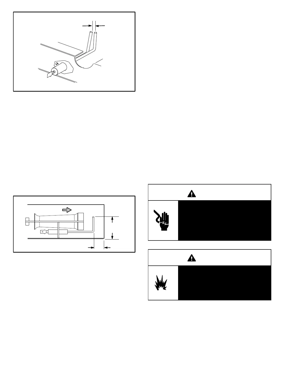
FIGURE 18
IGNITOR
SPARK GAP
SHOULD BE 1/8”
(3mm)
10-Flame Sensor Figure 19
A flame sensor is located under the left most side burner.
The sensor is mounted through a hole in the burner support
and the tip protrudes into the flame envelope of the left most
burner. The sensor assembly is fastened to burner supports
and can be removed for service without removing any part of
the burners.
When flame is sensed by the flame sensor (indicated by
microamp signal through the flame) sparking stops imme
diately or after the eight second trial for ignition. During op
eration, flame is sensed by current passed along the
ground electrode (located on the spark electrode),
through the flame and into the sensing electrode. The igni
tion control allows the gas valve to stay open as long as a
flame signal (current passed through the flame) is sensed.
FIGURE 19
SIDE VIEW SENSOR
1-3/4”
(45mm)
3/8”
(10mm)
Gas Flow
II-PLACEMENT AND INSTALLATION
Make sure the unit is installed in accordance with the in
stallation instructions and all applicable codes. See ac
cessories section for conditions requiring use of the op
tional roof mounting frame (T1CURB-AN or
K1CURB-AN).
III-START UP - OPERATION
A-Preliminary and Seasonal Checks
1- Make sure the unit is installed in accordance with the
installation instructions and applicable codes.
2- Inspect all electrical wiring, both field and factory installed
for loose connections. Tighten as required. Refer to unit di
agram located on inside of unit compressor access panel.
3- Check to ensure that refrigerant lines are in good
condition and do not rub against the cabinet or other
refrigerant lines.
4- Check voltage at the disconnect switch. Voltage must
be within the range listed on the nameplate. If not, con
sult the power company and have the voltage correct
ed before starting the unit.
5- Recheck voltage and amp draw with unit running. If
voltage is not within range listed on unit nameplate,
stop unit and consult power company. Refer to unit
nameplate for maximum rated load amps.
6- Inspect and adjust blower belt (see section on Blower
Compartment - Blower Belt Adjustment).
B-Heating Start up
FOR YOUR SAFETY READ BEFORE LIGHTING
WARNING
Electric shock hazard. Can cause injury
or death. Do not use this unit if any part
has been under water. Immediately call
a qualified service technician to inspect
the unit and to replace any part of the
control system and any gas control
which has been under water.
WARNING
Danger of explosion. Can cause injury
or product or property damage. If over
heating occurs or if gas supply fails to
shut off, shut off the manual gas valve
to the appliance before shutting off
electrical supply.

 Loading...