Page 40
B-Determining Unit CFM - Single-Speed, Direct Drive
Blowers
1- The following measurements must be made with air fil
ters in place.
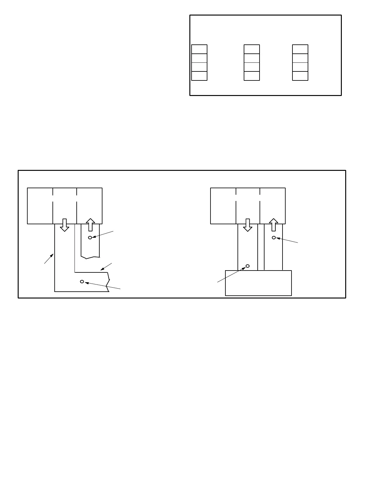
2- With all access panels in place, measure static pressure
external to unit (from supply to return). Add any addition
al air resistance for options and accessories shown in
accessory air resistance tables. Blower performance
data is based on static pressure readings taken in loca
tions shown in figure 7.
Note - Static pressure readings can vary if not taken where
shown.
3- Use figure 6 to determine the factory set blower speed.
BLOWER SPEED FACTORY SETTINGS
1
2
3
4
Com
Hi
Med
Low*
1
2
3
4
Com
Hi
Med*
Low
1
2
3
4
Com
Hi
Low*
Unused
*Factory Setting
036 Units
024, 030, &
048 Units
060 Units
FIGURE 6
4- Use direct drive blower tables, the measured static
pressure and the factory-set blower speed to deter
mine CFM. If CFM is lower or higher than the design
specified CFM, move the leads as shown in figure 8 for
208/230 volt units and figure 9 for 460/575 volt units.
LOCATION OF STATIC PRESSURE READINGS
SUPPLY AIR
READING
LOCATION
SUPPLY
RE
TURN
INSTALLATIONS WITH DUCTWORK
SUPPLY
RE
TURN
INSTALLATIONS WITH CEILING DIFFUSERS
MAIN
DUCT RUN
FIRST BRANCH
OFF OF MAIN RUN
DIFFUSER
ROOFTOP UNIT
ROOFTOP UNIT
SUPPLY AIR
READING
LOCATION
RETURN AIR
READING LOCATION
RETURN AIR
READING
LOCATION
FIGURE 7

 Loading...