Page 61
3-Testing Gas Supply Pressure
When testing gas supply pressure, connect test gauge to the
inlet pressure tap located on unit gas valve GV1. Test sup
ply gas pressure with unit firing at maximum rate (both
stages energized). Make sure the reading falls within the
range of the following values. Low pressure may result in
erratic operation or “underfire.” High pressure can result in
permanent damage to the gas valve or “overfire.” For nat
ural gas units, operating pressure at the unit gas connec
tion must be between 4.5”W.C. and 10.5”W.C. For L.P.
gas units, operating pressure at the unit gas connection
must be between 10.5”W.C. and 13.0”W.C.
On multiple unit installations, each unit should be checked
separately while operating at maximum rate, beginning with
the one closest to the supply gas main and progressing to
the one furthest from the main. Multiple units should also
be tested with and without the other units operating.
Supply pressure must fall within the range listed in the
previous paragraph.
4-Check and Adjust Manifold Pressure
After line pressure has been checked and adjusted, check
manifold pressure. Move test gauge to the outlet pressure
tap located on unit gas valve GV1. See figures 20 and 21
for location of pressure tap on the gas valve.
The manifold pressure is factory set and should not re
quire adjustment. If manifold pressure is incorrect and no
other source of improper manifold pressure can be found,
the valve must be replaced. See figure 20 and 21 for loca
tion of gas valve (manifold pressure) adjustment screw.
All gas valves are factory regulated. The gas valve should
completely and immediately cycle off in the event of gas or
power failure. The manual shut‐off knob can be used to im
mediately shut off gas supply.
CAUTION
For safety, connect a shut‐off valve between the
manometer and the gas tap to permit shut off of
gas pressure to the manometer.
Manifold Adjustment Procedure
1- Connect test gauge to the outlet pressure tap on the
gas valve. Start the unit (call for second stage heat)
and allow five minutes for the unit to reach steady
state.
2- While waiting for the unit to stabilize, notice the
flame. The flame should be stable without flashback
and should not lift from the burner heads. Natural
gas should burn basically blue with some clear
streaks. L.P. gas should burn mostly blue with some
clear yellow streaks.
3- After allowing the unit to stabilize for five minutes,
record the manifold pressure and compare to the val
ues below.
Natural Gas Units - Low Fire - 2.0” w.c.
Natural Gas Units - High Fire - 3.5” w.c.
LP Gas Units - Low Fire - 5.9” w.c.
LP Gas Units - High Fire - 10.5” w.c.
5-Proper Gas Flow
Furnace should operate at least 5 minutes before checking
gas flow. Determine time in seconds for two revolutions of
gas through the meter. (Two revolutions assures a more ac
curate time.) Divide by two and compare to time in table 24.
Seconds in table 24 are based on a 1 cu.ft. dial and gas val
ue of 1000 btu/ft
3
for natural and 2500 btu/ft
3
' for LP. Adjust
manifold pressure on gas valve to match time needed.
NOTE - To obtain accurate reading, shut off all other gas
appliances connected to meter.
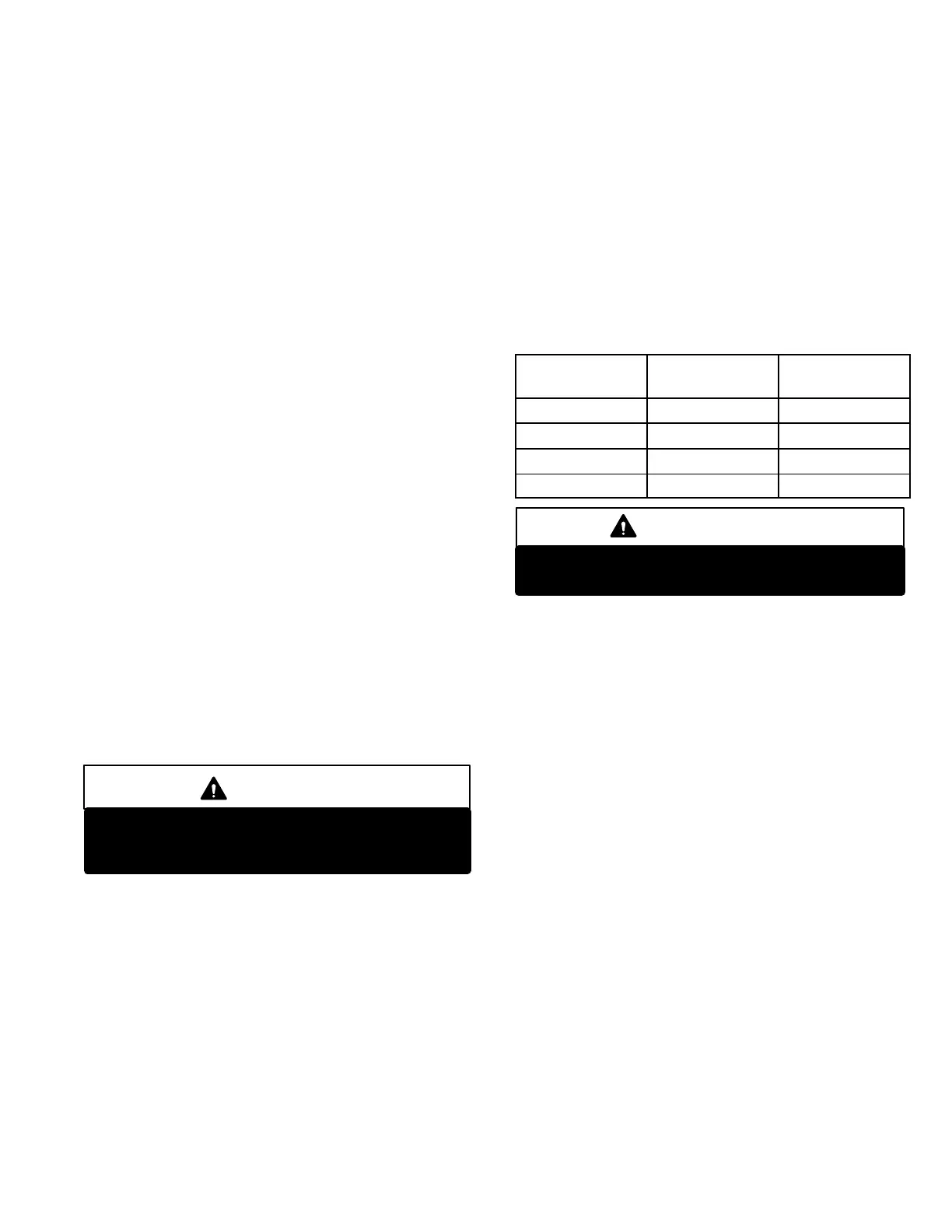
TABLE 24
Unit Input Rate
Seconds for
Natural
Seconds for
Propane
65,000 55 138
105,000 34 86
108,000 33 83
150,000 24 60
IMPORTANT
Disconnect heating demand as soon as an
accurate reading has been obtained.
6-Heat Exchanger
To Access or Remove Heat Exchanger From Unit:
1- Turn off gas and electric power.
2- Remove access panel(s) and unit center mullion.
3- Remove gas valve, manifold assembly and burn
ers.
4- Remove combustion air inducer. Pay careful attention
to the order in which gaskets and orifice are removed.
5- Support heat exchanger (to prevent it from falling
when final screws are removed.)
6- Remove screws supporting heat exchanger.
7- To install heat exchanger, reverse procedure. Be sure
to secure all wires and check plumbing and burner
plate for airtight seal. Screws must be torqued to 35
in.‐lbs. to ensure proper operation.
7-Flame Sensing
Flame current is an electrical current which passes from the
ignition control through the sensor electrode during unit op
eration. The current passes from the sensor through the
flame to the ground electrode (located on the flame elec
trode) to complete a safety circuit. The electrodes should be
located so the tips are at least 1/2” (12.7 mm) inside the
flame envelope. Do not bend electrodes. To measure flame
current, follow the procedure on the following page:
NOTE-Electrodes are not field adjustable. Any alter
ations to the electrode may create a hazardous con
dition that can cause property or personal injury.
1- Disconnect power to unit.

 Loading...